|
| Chapter 4 Parameters |
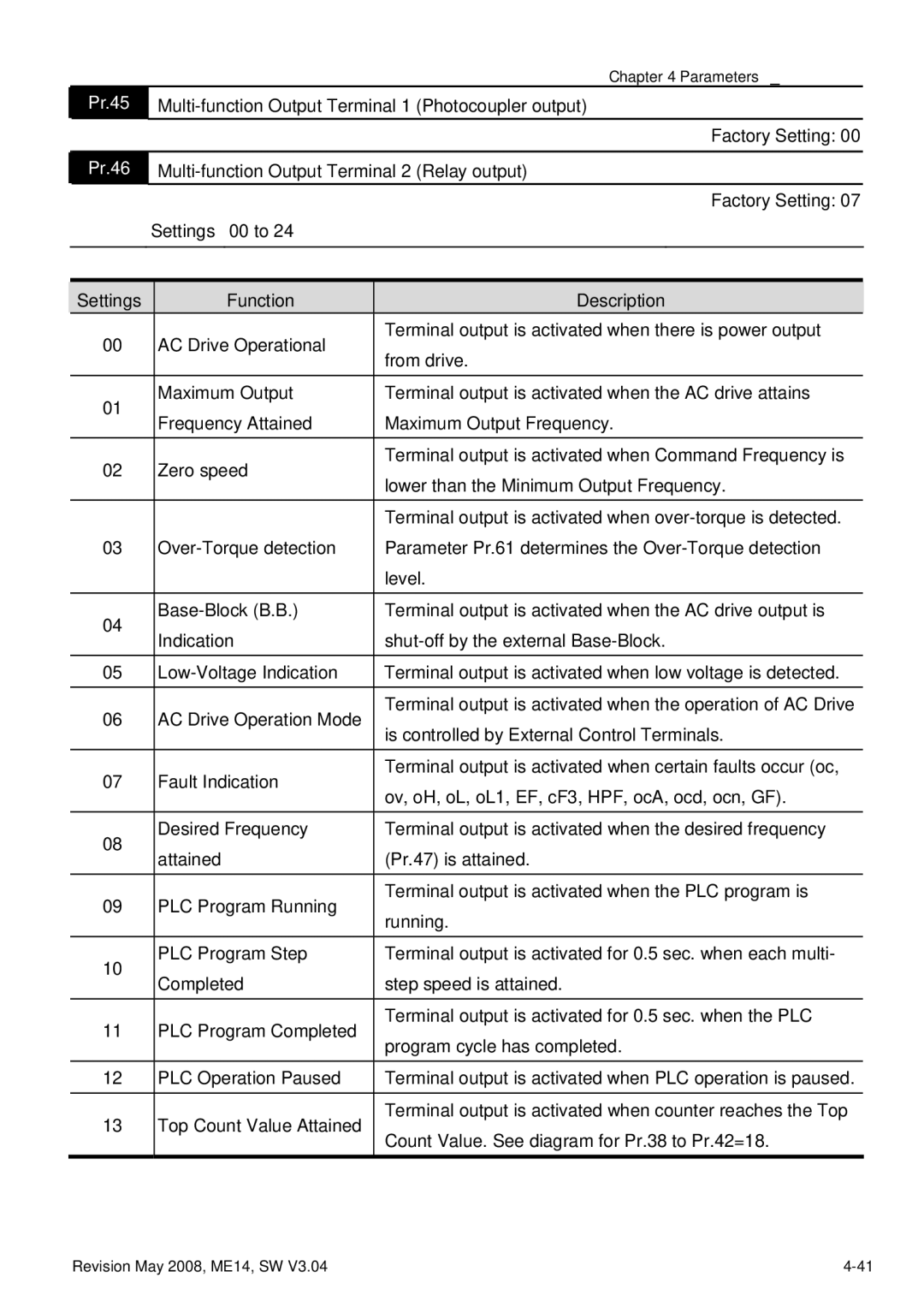
Pr.45 | ||
|
| Factory Setting: 00 |
Pr.46 | ||
|
| Factory Setting: 07 |
| Settings | 00 to 24 |
Settings | Function | Description | |
00 | AC Drive Operational | Terminal output is activated when there is power output | |
from drive. | |||
|
| ||
01 | Maximum Output | Terminal output is activated when the AC drive attains | |
Frequency Attained | Maximum Output Frequency. | ||
| |||
02 | Zero speed | Terminal output is activated when Command Frequency is | |
lower than the Minimum Output Frequency. | |||
|
| ||
|
| Terminal output is activated when | |
03 | Parameter Pr.61 determines the | ||
|
| level. | |
04 | Terminal output is activated when the AC drive output is | ||
Indication | |||
| |||
05 | Terminal output is activated when low voltage is detected. | ||
06 | AC Drive Operation Mode | Terminal output is activated when the operation of AC Drive | |
is controlled by External Control Terminals. | |||
|
| ||
07 | Fault Indication | Terminal output is activated when certain faults occur (oc, | |
ov, oH, oL, oL1, EF, cF3, HPF, ocA, ocd, ocn, GF). | |||
|
| ||
08 | Desired Frequency | Terminal output is activated when the desired frequency | |
attained | (Pr.47) is attained. | ||
| |||
09 | PLC Program Running | Terminal output is activated when the PLC program is | |
running. | |||
|
| ||
10 | PLC Program Step | Terminal output is activated for 0.5 sec. when each multi- | |
Completed | step speed is attained. | ||
| |||
11 | PLC Program Completed | Terminal output is activated for 0.5 sec. when the PLC | |
program cycle has completed. | |||
|
| ||
12 | PLC Operation Paused | Terminal output is activated when PLC operation is paused. | |
13 | Top Count Value Attained | Terminal output is activated when counter reaches the Top | |
Count Value. See diagram for Pr.38 to Pr.42=18. | |||
|
|
Revision May 2008, ME14, SW V3.04 |