|
|
|
| Appendix A Specifications |
|
|
|
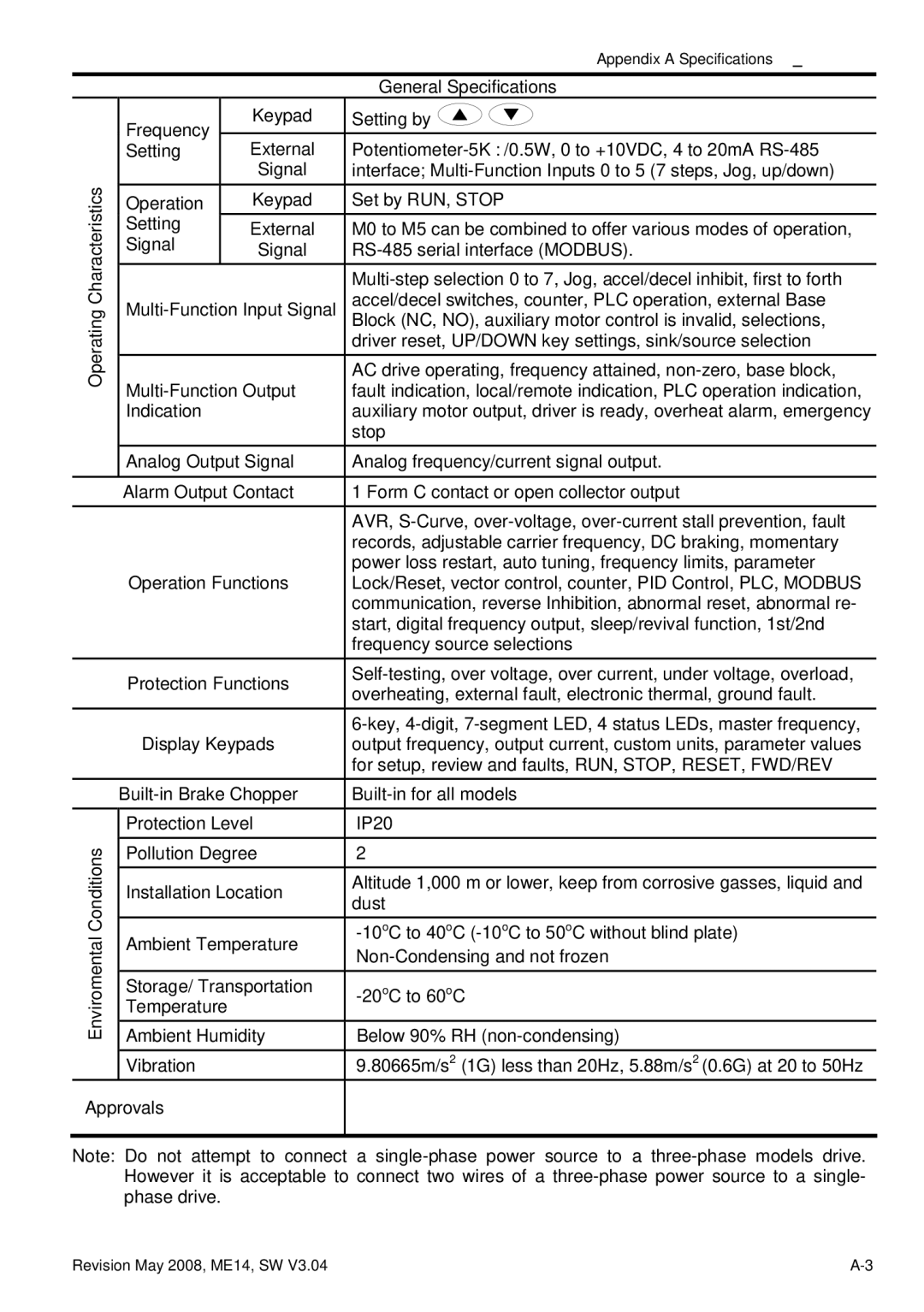
| General Specifications |
| Frequency |
| Keypad | Setting by |
|
| External | ||
| Setting |
| ||
Characteristics |
|
| Signal | interface; |
Operation |
| Keypad | Set by RUN, STOP | |
|
| |||
| Setting |
| External | M0 to M5 can be combined to offer various modes of operation, |
| Signal |
| Signal | |
|
|
|
| |
Operating | accel/decel switches, counter, PLC operation, external Base | |||
|
|
| Block (NC, NO), auxiliary motor control is invalid, selections, | |
|
|
|
| driver reset, UP/DOWN key settings, sink/source selection |
|
|
|
| AC drive operating, frequency attained, |
| fault indication, local/remote indication, PLC operation indication, | |||
| Indication |
| auxiliary motor output, driver is ready, overheat alarm, emergency | |
|
|
|
| stop |
| Analog Output Signal | Analog frequency/current signal output. | ||
|
|
| ||
| Alarm Output Contact | 1 Form C contact or open collector output | ||
|
|
|
| AVR, |
|
|
|
| records, adjustable carrier frequency, DC braking, momentary |
| Operation Functions | power loss restart, auto tuning, frequency limits, parameter | ||
| Lock/Reset, vector control, counter, PID Control, PLC, MODBUS | |||
|
|
|
| communication, reverse Inhibition, abnormal reset, abnormal re- |
|
|
|
| start, digital frequency output, sleep/revival function, 1st/2nd |
|
|
|
| frequency source selections |
| Protection Functions | |||
| overheating, external fault, electronic thermal, ground fault. | |||
|
|
|
| |
|
|
|
| |
| Display Keypads | output frequency, output current, custom units, parameter values | ||
|
|
|
| for setup, review and faults, RUN, STOP, RESET, FWD/REV |
| ||||
| Protection Level | IP20 | ||
Conditions | Pollution Degree | 2 | ||
|
|
| ||
| Installation Location | Altitude 1,000 m or lower, keep from corrosive gasses, liquid and | ||
|
|
|
| dust |
Enviromental | Ambient Temperature | |||
|
|
| ||
|
|
|
| |
| Storage/ Transportation | |||
| Temperature |
|
| |
| Ambient Humidity | Below 90% RH | ||
| Vibration |
| 9.80665m/s2 (1G) less than 20Hz, 5.88m/s2 (0.6G) at 20 to 50Hz | |
Approvals |
|
| ||
|
|
|
|
|
Note: Do not attempt to connect a
Revision May 2008, ME14, SW V3.04 |