Page
Page
Page
Preface
Page
Table of Contents
Parameters
Troubleshooting
Keypad and Start Up
Appendix a Specifications Appendix B Accessories
Fault Code Information and Maintenance
Appendix C How to Select the Right AC Motor Drive
Introduction
Series Number Explanation D007M23A0 T 5
Receiving and Inspection
Nameplate Information
Model Explanation
External Parts and Labels
RST Side UVW Side
Remove Instructions Remove Keypad Remove Front Cover
Minimum Mounting Clearances
Preparation for Installation and Wiring Ambient Conditions
50 mm 150mm
Model Name
Dimensions
This page intentionally left blank
Installation and Wiring
L1 NFB
Basic Wiring Diagram
Excellent
Good Not allowed
Appendix a
External Wiring
Explanation of Terminal Function
Terminal Symbol
Mains power terminals R/L1, S/L2, T/L3
Main Circuit Main Circuit Connection
Output terminals for main circuit U, V, W
Terminals B1, B2 for connecting external brake unit
AWG
Main Circuit Terminals
RB-RC
Control Terminal Wiring Factory Settings
RA-RC
M0~M5-GND
AVI
ACI
AFM
Digital outputs MO1
MO1
MCM
Analog inputs AVI, ACI
General
Keypad Description of the Digital Keypad
Keypad and Start Up
Displayed Message
How to Operate the Digital Keypad LC-M02E
LED
LC-M02E
Keypad and Start Up
Trial Run
Operation Method
Check following items
Parameters
Setting
Summary of Parameter Settings
Parameter Explanation Settings Factory
Parameter Explanation Settings Factory
01 M0 RUN/STOP, M1 REV/FWD
Reset
00 M0 FWD/STOP, M1 REV/STOP
Second Source for Frequency Command
FLA
Parameter Explanation Settings Factory
CFA
PLC FWD/REV
Only
Input positive PID feedback, PV from AVI
Parameter Explanation Settings Factory
Parameter Explanation Settings Factory
Multi-step Operation Applications Purpose Functions
Parameter Settings for Applications
DC Braking before Running Applications Purpose Functions
Overheat Warning Applications Purpose
Two-wire/three-wire Applications Purpose
Wire
Operation Command Applications Purpose
Parameters
Parameters
Parameters
Parameters
Pr.02 Stop Method
Description of Parameter Settings
Pr.00 Source of Frequency Command
Pr.01
Pr.04
Pr.03
Pr.09
Pr.06
Pr.07
Pr.08
Commonly used V/F Setting General Purpose
Pr.13
Pr.10
Pr.11
Pr.12
Pr.16
Pr.14
Pr.15
Pr.20
Pr.17
Pr.18
Pr.19
Pr.26
Pr.24 Reverse Operation Inhibition
Pr.28
Pr.27
Pr.31
Pr.29
Pr.30
Pr.35
Pr.33
Pr.34
Pr.37
Pr.36
Explanations
Pr.38
Pr.42
Settings Function Description
Pr.39
Pr.40
Settings Function Description
GND
First or Second
Mx Close Run PLC
Parameter value 18 programs Multi-Function Input Terminal
Contact N.C. is reverse, once this function is set
Pr.44
Pr.43 Analog Output Signal
Pr.46
Pr.45
MO1
Pr.49
Pr.51 Potentiometer Reverse Motion Enable
Pr.47
Pr.48
Example
Max Output Pr.03 Freq 60Hz Bias 10Hz Pr =
FWD
Pr.55
Pr.52
Pr.53
Pr.54
Pr.59
Pr.58
Pr.64
Pr.60
Pr.61
Pr.62
Pr.66
Pr.65
Pr.70
Pr.67
Pr.68
Pr.69
Pr.75 Third Most Recent Fault Record
Pr.73 Present Fault Record Pr.74
Pr.77
Pr.76 Parameter Lock and Configuration
Pr.78 PLC Operation Mode
Program input off and then back on
Example 3 Pr.78 = 03 Execute one cycle step by step
Example 2 Pr.78 = 02 Continuously executes program cycles
REV
Application Note
Weights =Forward =Reverse Bit
Pr.83
Pr.80
Pr.81
Pr.82
Computer Control
Pr.89 Transmission Speed Baud rate
Pr.92 Communication Protocol
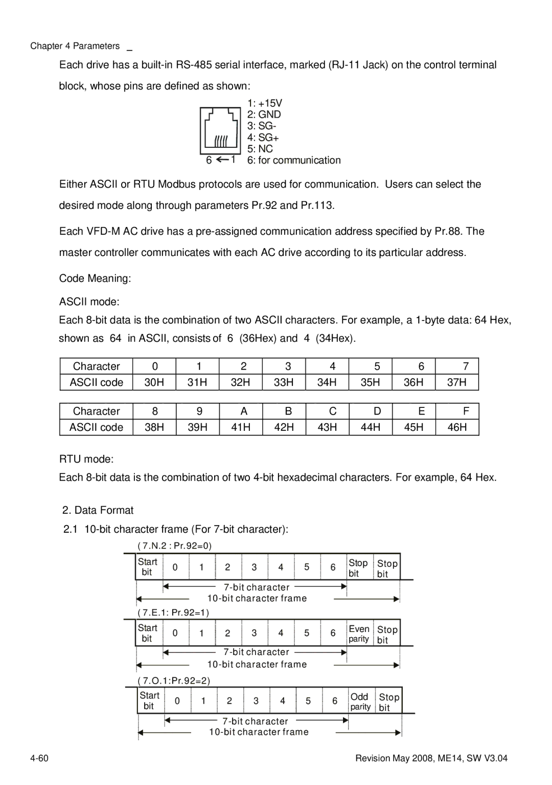
Data Format
+15V 2 GND SG- 4 SG+ 6 for communication
Communication Protocol
Ascii mode
END
RTU mode
Start
ADR
F7H
STX ADR
LRC CHK
6FH
‘6’
Starting data address ‘0’ ‘1’
CDH
0FH
A0H
B2H
Starting address 21H 02H
Read at one time
CPU or analog circuit failure cF3
Parameters
Void main Int OutportbPORT+MCR,0x08
Pr.96
Pr.93 Accel 1 to Accel 2 Frequency Transition Pr.94
Pr.95
Pr.100
Pr.97
Pr.98
Pr.99
Pr.104 R1 Value
Pr.103 Auto Tune Motor parameters
Pr.108
Pr.105 Control Mode
Pr.106
Pr.107
Cooling Fan Control
Pr.112
Pr.113
Integral Time
PID Feedback Terminal Selection
Factory Setting 100 %
PID Offset Level Settings To 50.0 %
Inverts Reference Signal 0-20mA
External Up/Down Selection
Wake Up Frequency Unit 0.10Hz Settings 00 to 400.0 Hz
Save
Parameters
Pr.156
Pr.157 Communication Mode Selection
Reserved
Pr.155
Parameters
This page intentionally left blank
Over Current OC
Troubleshooting
Over Voltage OV
Ground Fault
Low Voltage Lv
Overload
Over Heat OH1
Keypad Display is Abnormal
Phase Loss PHL
Motor cannot Run
Motor Speed cannot be Changed
Motor does not Run as Expected
Motor Stalls during Acceleration
Environmental Condition
Electromagnetic/Induction Noise
Affecting Other Machines
Serial reactor Phase lead capacitor
Fault Name Fault Descriptions
Fault Code Information
Common Problems and Solutions
Fault Name Fault Descriptions Corrective Actions
Fault Name Fault Descriptions
Fault Name Fault Descriptions
Maintenance and Inspections
Reset
Voltage Maintenance Check Items Methods and Criterion
Change of copper plate
Keypad Maintenance Check Items Methods and Criterion
Main circuit Maintenance Check Items Methods and Criterion
One
One
Daily
230V Class
Voltage Class
115V Class
575V Class
General Specifications
460V Class
Analog Output Signal Analog frequency/current signal output
This page intentionally left blank
All Brake Resistors & Brake Units Used in AC Motor Drives
Appendix B Accessories
Appendix B Accessories
Dimensions are in millimeter
Dimensions and Weights for Brake Resistors& Brake Units
Appendix B Accessories
Non-fuse Circuit Breaker Chart
Fuse Specification Chart
AC Output Reactor Recommended Value
AC Reactor AC Input Reactor Recommended Value
Applications
Mains circuit
Diagram B
Zero Phase Reactor RF220X00A
Diagram a
VFD-M Programming
Remote Controller RC-01
Explanation of Display Message
PU06 Description of the Digital Keypad VFD-PU06
XX-XX
Operation Flow Chart
16TDT1W4S
AMD EMI Filter Cross Reference
40TDS4W4B
Choose suitable motor cable and precautions
Length of motor cable
EMI Filter RF015M21AA / RF022M43AA
Appendix B Accessories
Din Rail Din Rail-DR01 Adapter
Din Rail-DR02 Adapter
Related Specification
Appendix C How to Select the Right AC Motor Drive
Capacity Formulas
When one AC motor drive operates one motor
When one AC motor drive operates more than one motor
⋅ IM ≤ the rated current of AC motor drive a
Selection Note
General Precaution
Parameter Settings Note
Standard motor
How to Choose a Suitable Motor
、 Pole-changing Dahlander motor
Special motors
Motor torque
Power Transmission Mechanism
This page intentionally left blank


 1 6: for communication