|
|
|
|
|
|
|
|
|
|
|
| Chapter 4 Parameters | |||||||
| Hz |
|
|
|
|
|
| Hz | |||||||||||
Freq. |
|
|
|
|
|
|
|
|
| Freq. |
|
| |||||||
Motor |
|
|
|
|
|
|
|
|
| Motor | |||||||||
Speed |
|
|
|
|
|
|
|
|
| Speed | |||||||||
|
|
|
|
|
|
|
| Time |
|
|
|
|
|
|
|
| Time | ||
|
|
|
|
| Stops according |
|
|
|
|
|
| Free running |
|
| |||||
|
|
|
|
|
|
|
|
|
|
|
|
|
|
|
| ||||
|
|
|
|
| to deceleration |
|
|
|
|
|
|
|
|
| to stop |
|
|
|
|
Operation |
| ON |
| time |
|
|
|
|
| ON OFF | |||||||||
|
| OFF |
|
| |||||||||||||||
command |
|
|
|
| |||||||||||||||
|
|
|
|
|
|
|
|
|
|
| |||||||||
|
|
|
| Ramp |
|
|
| Coast | |||||||||||
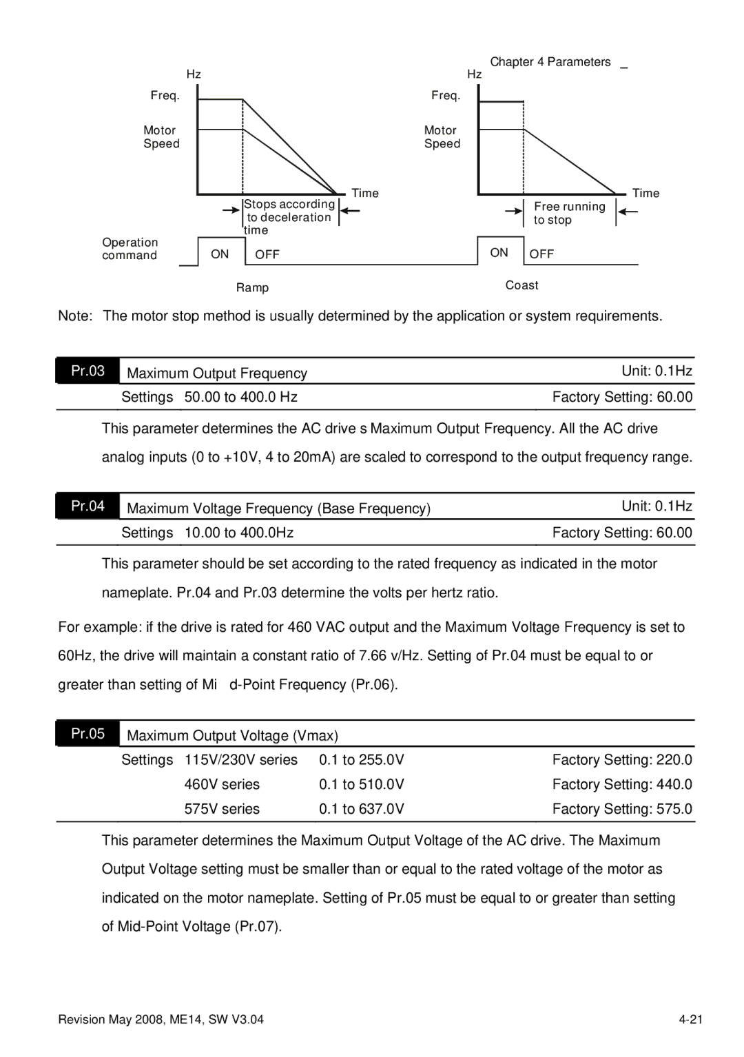
Note: The motor stop method is usually determined by the application or system requirements.
Pr.03 | Maximum Output Frequency | Unit: 0.1Hz |
| Settings 50.00 to 400.0 Hz | Factory Setting: 60.00 |
|
|
|
This parameter determines the AC drive’s Maximum Output Frequency. All the AC drive analog inputs (0 to +10V, 4 to 20mA) are scaled to correspond to the output frequency range.
| Pr.04 | Maximum Voltage Frequency (Base Frequency) | Unit: 0.1Hz |
|
| Settings 10.00 to 400.0Hz | Factory Setting: 60.00 |
This parameter should be set according to the rated frequency as indicated in the motor nameplate. Pr.04 and Pr.03 determine the volts per hertz ratio.
For example: if the drive is rated for 460 VAC output and the Maximum Voltage Frequency is set to 60Hz, the drive will maintain a constant ratio of 7.66 v/Hz. Setting of Pr.04 must be equal to or
greater than setting of Mid-Point Frequency (Pr.06).
Pr.05 Maximum Output Voltage (Vmax)
Settings 115V/230V series | 0.1 to 255.0V | Factory Setting: 220.0 |
460V series | 0.1 to 510.0V | Factory Setting: 440.0 |
575V series | 0.1 to 637.0V | Factory Setting: 575.0 |
|
|
|
This parameter determines the Maximum Output Voltage of the AC drive. The Maximum
Output Voltage setting must be smaller than or equal to the rated voltage of the motor as
indicated on the motor nameplate. Setting of Pr.05 must be equal to or greater than setting
of
Revision May 2008, ME14, SW V3.04 |