Operator Panel
v
vLEDs for power on, attention, SCSI activity, and LAN activity
vButtons for power on, system reset, and service processor reset
System Reset
Dumps AIX (if dump is enabled) and reboots.
Service Processor Reset
Resets the service processor (standby mode).
Input/Output Ports
vOne
vKeyboard
vMouse
vTwo Ultra3 SCSI (one to internal
vIntegrated Drive Electronics (IDE)
vTwo 10/100 Ethernet (IEEE 802.3 compliant)
vThree serial ports. Serial port 1 (S1) has two physical connectors, one
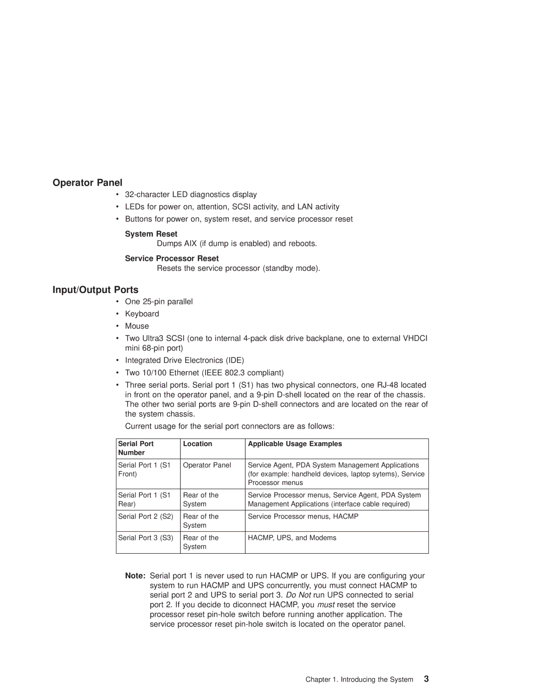
Current usage for the serial port connectors are as follows:
Serial Port | Location | Applicable Usage Examples |
Number |
|
|
|
|
|
Serial Port 1 (S1 | Operator Panel | Service Agent, PDA System Management Applications |
Front) |
| (for example: handheld devices, laptop sytems), Service |
|
| Processor menus |
|
|
|
Serial Port 1 (S1 | Rear of the | Service Processor menus, Service Agent, PDA System |
Rear) | System | Management Applications (interface cable required) |
|
|
|
Serial Port 2 (S2) | Rear of the | Service Processor menus, HACMP |
| System |
|
|
|
|
Serial Port 3 (S3) | Rear of the | HACMP, UPS, and Modems |
| System |
|
|
|
|
Note: Serial port 1 is never used to run HACMP or UPS. If you are configuring your system to run HACMP and UPS concurrently, you must connect HACMP to serial port 2 and UPS to serial port 3. Do Not run UPS connected to serial port 2. If you decide to diconnect HACMP, you must reset the service processor reset
Chapter 1. Introducing the System 3
