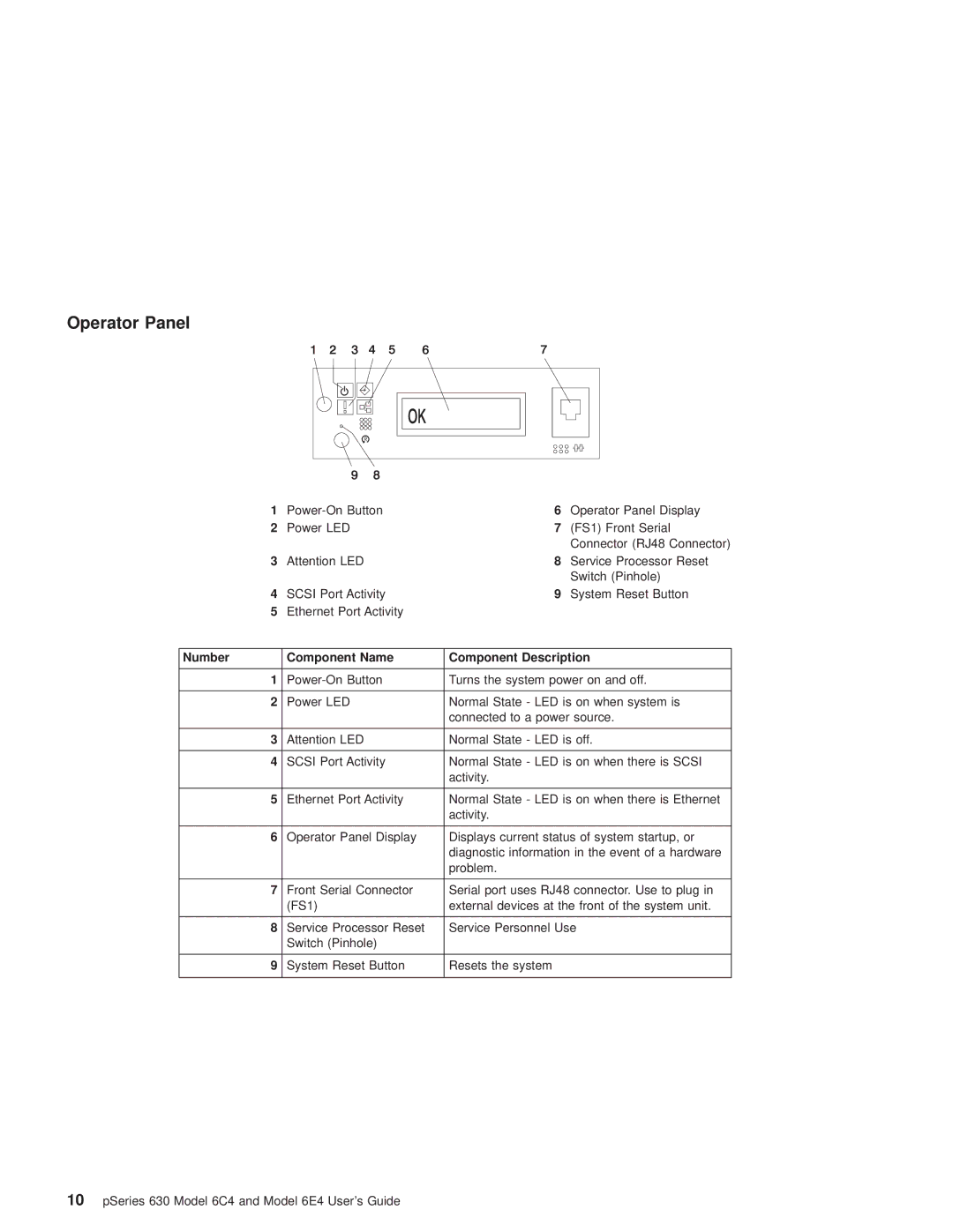
Operator Panel
1 | 6 | Operator Panel Display | |
2 | Power LED | 7 | (FS1) Front Serial |
|
|
| Connector (RJ48 Connector) |
3 | Attention LED | 8 | Service Processor Reset |
|
|
| Switch (Pinhole) |
4 | SCSI Port Activity | 9 | System Reset Button |
5 | Ethernet Port Activity |
|
|
|
|
| |
Number | Component Name | Component Description | |
|
|
| |
1 | Turns the system power on and off. | ||
|
|
| |
2 | Power LED | Normal State - LED is on when system is | |
|
| connected to a power source. | |
|
|
| |
3 | Attention LED | Normal State - LED is off. | |
|
|
| |
4 | SCSI Port Activity | Normal State - LED is on when there is SCSI | |
|
| activity. |
|
|
|
| |
5 | Ethernet Port Activity | Normal State - LED is on when there is Ethernet | |
|
| activity. |
|
|
|
| |
6 | Operator Panel Display | Displays current status of system startup, or | |
|
| diagnostic information in the event of a hardware | |
|
| problem. |
|
|
|
| |
7 | Front Serial Connector | Serial port uses RJ48 connector. Use to plug in | |
| (FS1) | external devices at the front of the system unit. | |
|
|
| |
8 | Service Processor Reset | Service Personnel Use | |
| Switch (Pinhole) |
|
|
|
|
|
|
9 | System Reset Button | Resets the system |
|
|
|
|
|
10pSeries 630 Model 6C4 and Model 6E4 User's Guide