CHAPTER 5 EXAMPLES OF SETUP ON NETWORKS
DIGITAL PRIVATE LINE NETWORK EXAMPLE (E1)
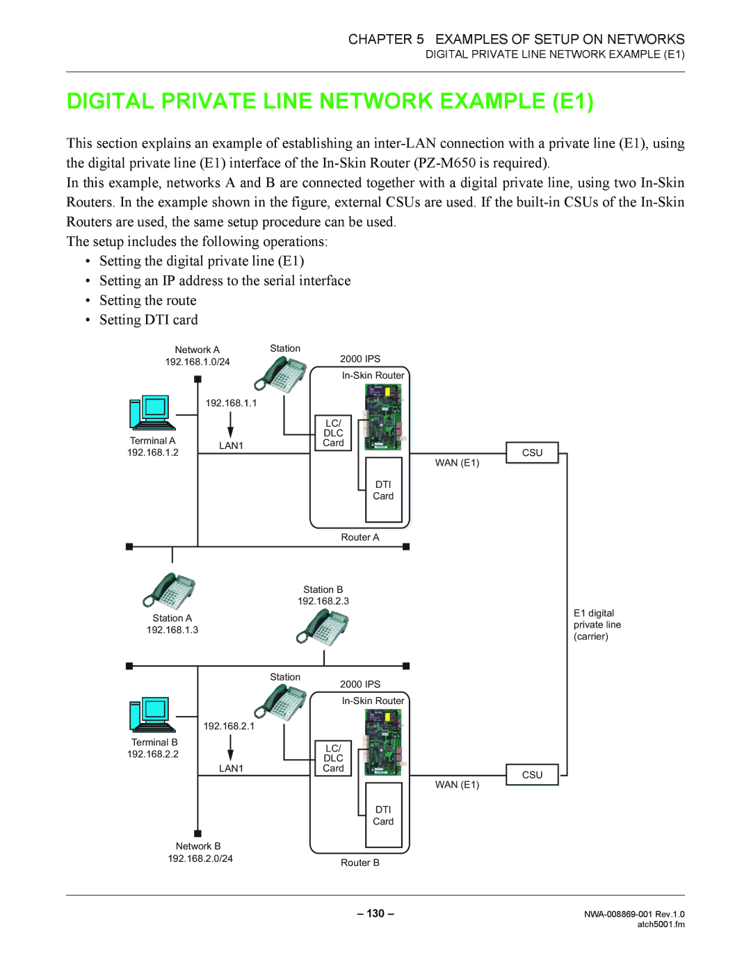
DIGITAL PRIVATE LINE NETWORK EXAMPLE (E1)
This section explains an example of establishing an
In this example, networks A and B are connected together with a digital private line, using two
The setup includes the following operations:
•Setting the digital private line (E1)
•Setting an IP address to the serial interface
•Setting the route
•Setting DTI card
|
| Network A | Station | |||||||||||
192.168.1.0/24 |
|
|
| 2000 IPS | ||||||||||
|
|
|
|
|
|
|
|
|
| |||||
|
|
|
|
|
|
|
| |||||||
|
|
|
|
|
| |||||||||
|
|
|
| 192.168.1.1 |
|
|
|
|
|
|
|
|
| |
|
|
|
|
|
|
|
|
|
|
|
|
| ||
|
|
|
|
|
|
|
|
|
|
|
|
|
|
|
|
|
|
|
|
|
|
| LC/ |
|
|
|
|
|
|
Terminal A |
|
|
|
| DLC |
|
|
|
|
| ||||
|
|
|
|
|
|
|
|
|
| |||||
LAN1 |
|
| Card |
|
|
|
|
| ||||||
192.168.1.2 |
|
|
|
|
|
|
|
|
| |||||
|
|
|
|
|
|
|
|
|
| WAN (E1) | ||||
|
|
|
|
|
|
|
|
|
|
|
|
|
| |
|
|
|
|
|
|
|
|
|
|
|
| DTI |
| |
|
|
|
|
|
|
|
|
|
|
|
| Card |
| |
|
|
|
|
|
|
|
|
|
|
| ||||
|
|
|
|
|
|
|
| Router A | ||||||
|
|
|
|
|
|
|
|
|
|
|
|
|
|
|
|
|
|
|
|
|
|
|
|
|
|
|
|
|
|
Station B
192.168.2.3
Station A
192.168.1.3
Station
2000 IPS
192.168.2.1 |
|
| |
|
| ||
|
|
| |
Terminal B |
|
|
|
|
| LC/ | |
192.168.2.2 |
|
| |
|
| DLC | |
|
|
| |
LAN1 | Card | ||
|
|
|
|
WAN (E1)
DTI
Card
Network B |
|
192.168.2.0/24 | Router B |
|
CSU |
CSU |
E1 digital private line (carrier)
– 130 – | |
| atch5001.fm |