CHAPTER 2 INSTALLATION
INSTALLATION PROCEDURE
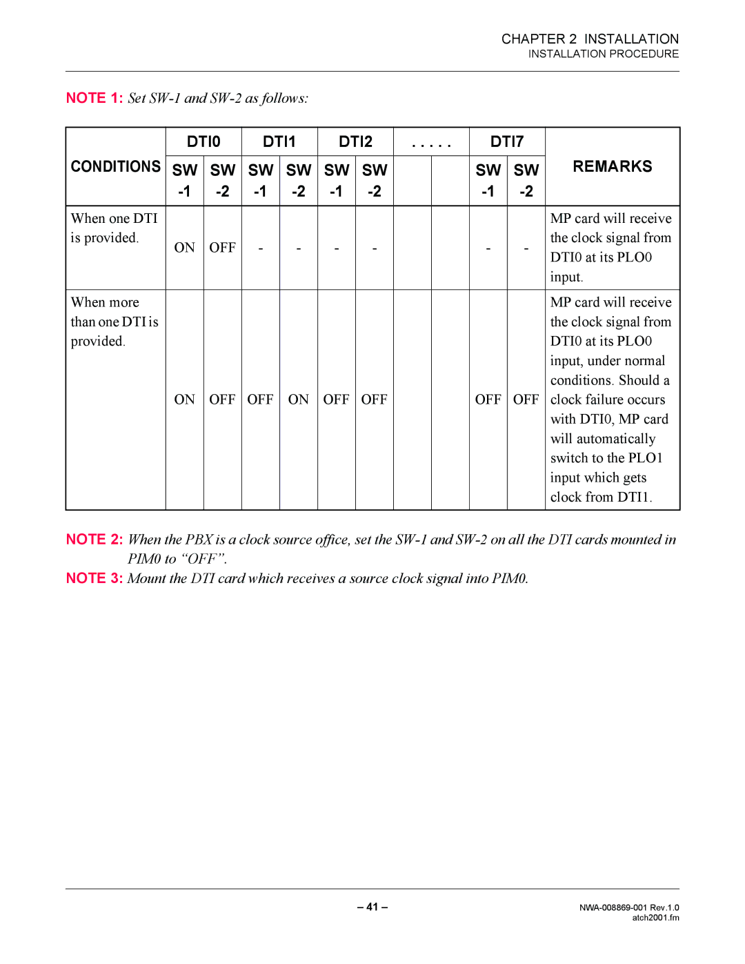
NOTE 1: Set
| DTI0 | DTI1 | DTI2 | . . . . . | DTI7 |
| |||||
CONDITIONS |
|
|
|
|
|
|
|
|
|
| REMARKS |
SW | SW | SW | SW | SW | SW |
|
| SW | SW | ||
|
|
|
| ||||||||
|
|
|
|
|
|
|
|
|
|
|
|
When one DTI |
|
|
|
|
|
|
|
|
|
| MP card will receive |
is provided. | ON | OFF | - | - | - | - |
|
| - | - | the clock signal from |
|
|
| DTI0 at its PLO0 | ||||||||
|
|
|
|
|
|
|
|
|
|
| |
|
|
|
|
|
|
|
|
|
|
| input. |
|
|
|
|
|
|
|
|
|
|
|
|
When more |
|
|
|
|
|
|
|
|
|
| MP card will receive |
than one DTI is |
|
|
|
|
|
|
|
|
|
| the clock signal from |
provided. |
|
|
|
|
|
|
|
|
|
| DTI0 at its PLO0 |
|
|
|
|
|
|
|
|
|
|
| input, under normal |
|
|
|
|
|
|
|
|
|
|
| conditions. Should a |
| ON | OFF | OFF | ON | OFF | OFF |
|
| OFF | OFF | clock failure occurs |
|
|
|
|
|
|
|
|
|
|
| with DTI0, MP card |
|
|
|
|
|
|
|
|
|
|
| will automatically |
|
|
|
|
|
|
|
|
|
|
| switch to the PLO1 |
|
|
|
|
|
|
|
|
|
|
| input which gets |
|
|
|
|
|
|
|
|
|
|
| clock from DTI1. |
|
|
|
|
|
|
|
|
|
|
|
|
NOTE 2: When the PBX is a clock source office, set the
NOTE 3: Mount the DTI card which receives a source clock signal into PIM0.
– 41 – | |
| atch2001.fm |