CHAPTER 2 INSTALLATION
INSTALLATION PROCEDURE
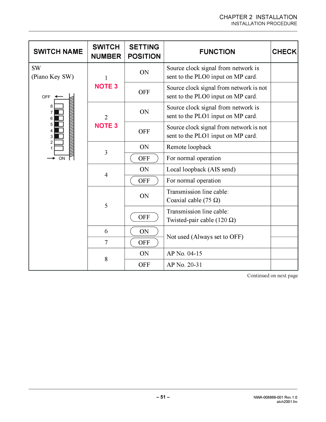
SWITCH NAME | SWITCH | SETTING | FUNCTION | CHECK | ||||||
NUMBER | POSITION | |||||||||
|
|
|
|
|
|
|
| |||
|
|
|
|
|
|
|
|
|
| |
SW |
| ON | Source clock signal from network is |
| ||||||
(Piano Key SW) | 1 | sent to the PLO0 input on MP card. |
| |||||||
|
| |||||||||
|
|
|
|
|
| NOTE 3 | OFF | Source clock signal from network is not |
| |
OFF |
|
|
| sent to the PLO0 input on MP card. |
| |||||
|
|
|
| |||||||
|
|
|
|
| ||||||
|
|
|
|
|
|
|
|
|
| |
8 |
|
|
|
|
|
| ON | Source clock signal from network is |
| |
|
|
|
|
|
|
| ||||
7 |
|
|
|
|
| 2 | sent to the PLO1 input on MP card. |
| ||
|
|
|
|
|
| |||||
6 |
|
|
|
|
|
|
| |||
|
|
|
|
|
|
| ||||
5 |
|
|
|
|
| NOTE 3 |
|
|
| |
|
|
|
|
|
| Source clock signal from network is not |
| |||
4 |
|
|
|
|
| OFF |
| |||
|
|
|
|
|
| |||||
|
|
|
|
|
| sent to the PLO1 input on MP card. |
| |||
3 |
|
|
|
|
|
|
|
| ||
|
|
|
|
|
|
|
| |||
2 |
|
|
|
|
|
|
|
|
| |
| ON | Remote loopback |
| |||||||
1 |
|
|
|
|
| 3 |
| |||
|
|
|
|
|
|
|
|
| ||
|
| ON |
|
| OFF | For normal operation |
| |||
|
|
|
|
|
| |||||
|
|
|
| |||||||
|
|
|
|
|
|
|
|
|
| |
|
|
|
|
|
| 4 | ON | Local loopback (AIS send) |
| |
|
|
|
|
|
|
|
|
| ||
|
|
|
|
|
| OFF | For normal operation |
| ||
|
|
|
|
|
|
|
| |||
|
|
|
|
|
|
|
|
|
| |
|
|
|
|
|
|
| ON | Transmission line cable: |
| |
|
|
|
|
|
|
| Coaxial cable (75 Ω) |
| ||
|
|
|
|
|
| 5 |
|
| ||
|
|
|
|
|
|
|
|
| ||
|
|
|
|
|
| OFF | Transmission line cable: |
| ||
|
|
|
|
|
|
|
| |||
|
|
|
|
|
|
|
| |||
|
|
|
|
|
|
|
|
| ||
|
|
|
|
|
|
|
|
|
| |
|
|
|
|
|
| 6 | ON | Not used (Always set to OFF) |
| |
|
|
|
|
|
|
|
|
| ||
|
|
|
|
|
| 7 | OFF |
| ||
|
|
|
|
|
|
|
| |||
|
|
|
|
|
|
|
|
|
| |
|
|
|
|
|
| 8 | ON | AP No. |
| |
|
|
|
|
|
|
|
|
| ||
|
|
|
|
|
| OFF | AP No. |
| ||
|
|
|
|
|
|
|
| |||
|
|
|
|
|
|
|
|
|
| |
Continued on next page
– 51 – | |
| atch2001.fm |
