CHAPTER 2 INSTALLATION
INSTALLATION PROCEDURE
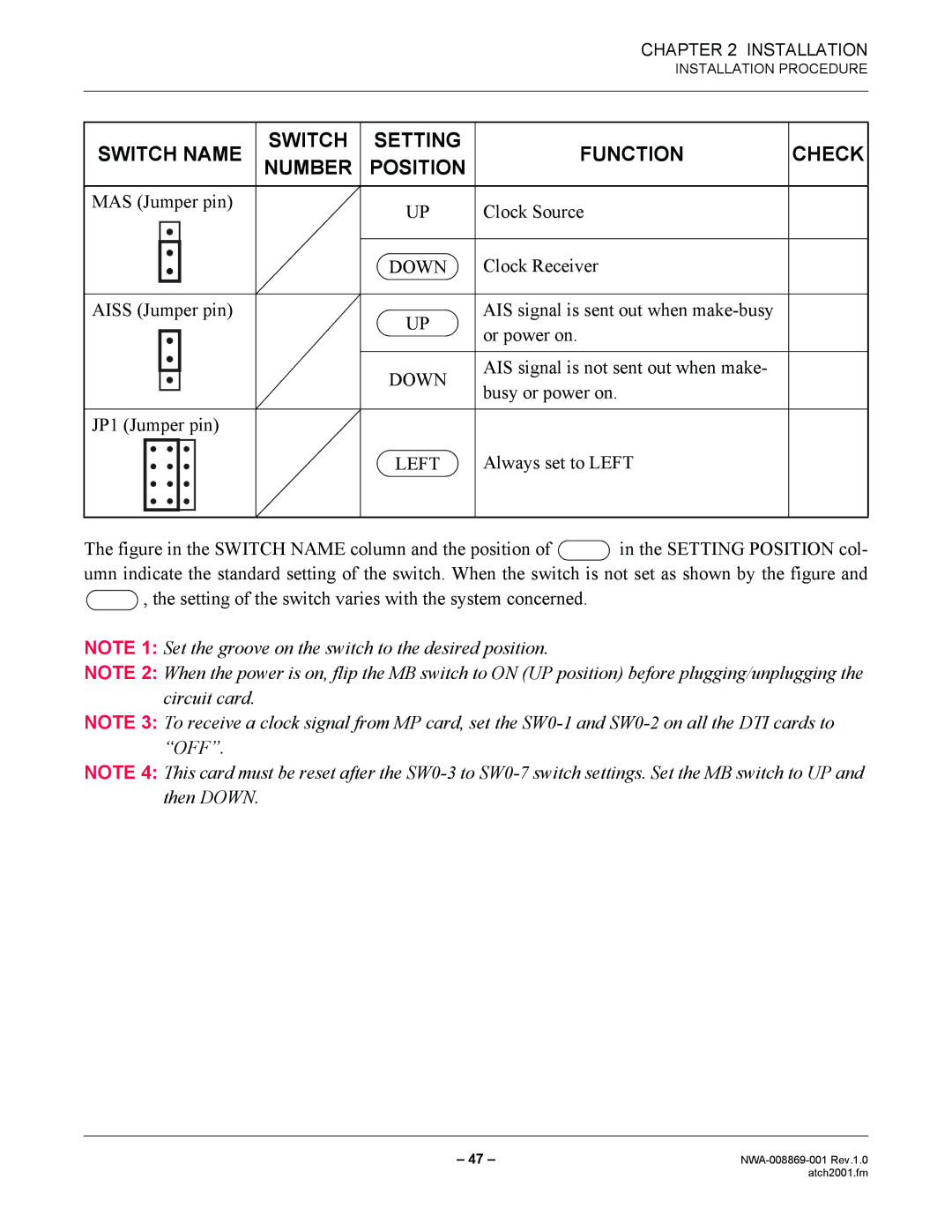
SWITCH NAME | SWITCH | SETTING | FUNCTION | CHECK | |||
NUMBER | POSITION | ||||||
|
|
|
|
|
|
|
|
MAS (Jumper pin) |
| UP | Clock Source |
| |||
|
|
|
|
|
| ||
|
|
|
|
|
|
|
|
|
|
|
|
| DOWN | Clock Receiver |
|
|
|
|
|
|
| ||
|
|
|
|
|
|
|
|
AISS (Jumper pin) |
| UP | AIS signal is sent out when |
| |||
|
|
|
|
| or power on. |
| |
|
|
|
|
|
|
| |
|
|
|
|
|
|
|
|
|
|
|
|
| DOWN | AIS signal is not sent out when make- |
|
|
|
|
|
|
| ||
|
|
|
|
| busy or power on. |
| |
|
|
|
|
|
|
| |
|
|
|
|
|
|
|
|
JP1 (Jumper pin) |
|
|
|
| |||
|
|
|
|
| LEFT | Always set to LEFT |
|
|
|
|
|
|
| ||
|
|
|
|
|
|
|
|
|
|
|
|
|
|
|
|
The figure in the SWITCH NAME column and the position of  in the SETTING POSITION col- umn indicate the standard setting of the switch. When the switch is not set as shown by the figure and
  , the setting of the switch varies with the system concerned.
NOTE 1: Set the groove on the switch to the desired position.
NOTE 2: When the power is on, flip the MB switch to ON (UP position) before plugging/unplugging the circuit card.
NOTE 3: To receive a clock signal from MP card, set the
NOTE 4: This card must be reset after the
– 47 – | |
| atch2001.fm |