CHAPTER 2 INSTALLATION
INSTALLATION PROCEDURE
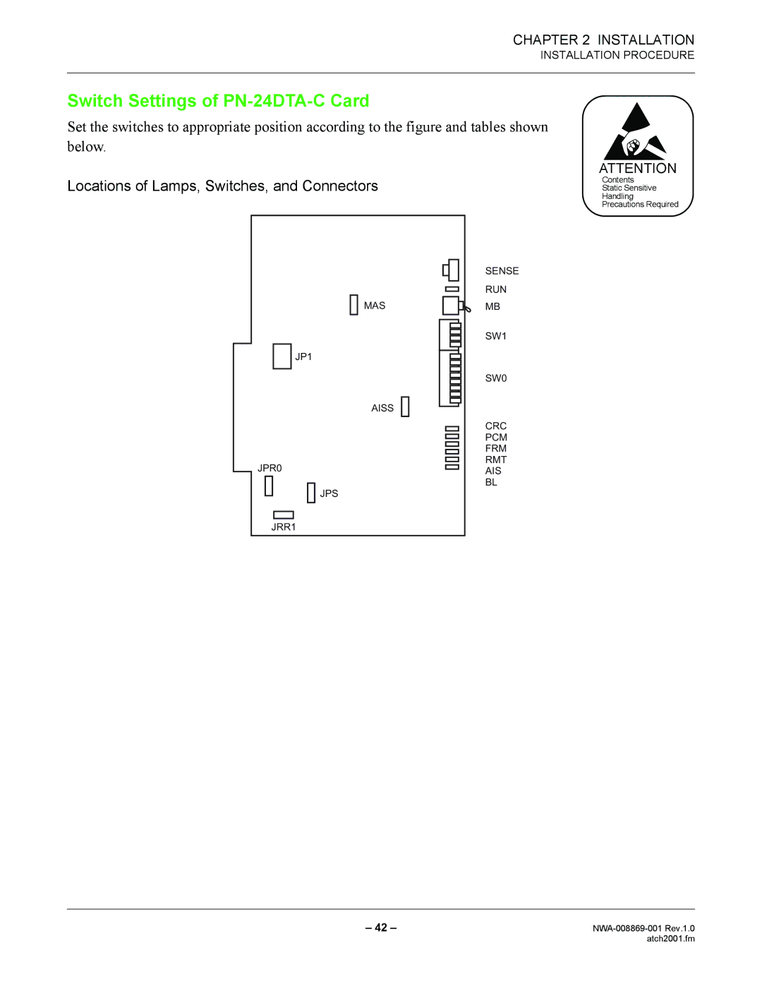
Switch Settings of PN-24DTA-C Card
Set the switches to appropriate position according to the figure and tables shown below.
Locations of Lamps, Switches, and Connectors
|
|
|
|
|
|
|
|
|
|
|
|
|
| SENSE |
|
|
|
|
|
|
|
|
|
|
|
|
|
| |
|
|
|
|
|
|
|
|
|
|
|
|
|
| RUN |
|
|
|
|
|
|
|
|
|
|
|
|
|
| |
|
|
|
|
|
|
| MAS |
|
|
|
| MB | ||
|
|
|
|
|
|
|
|
|
|
|
|
|
| SW1 |
|
|
|
|
|
|
|
|
|
|
|
|
|
| |
|
|
|
|
|
|
|
|
|
|
|
|
|
| |
|
|
| JP1 |
|
|
|
|
| ||||||
|
|
|
|
|
|
|
|
|
|
|
|
|
| SW0 |
|
|
|
|
|
|
|
|
|
|
|
|
|
| |
|
|
|
|
|
|
| AISS |
|
|
|
|
|
| CRC |
|
|
|
|
|
|
|
|
|
|
|
|
| ||
|
|
|
|
|
|
|
|
|
|
|
|
| ||
|
|
|
|
|
|
|
|
|
|
|
|
|
| |
|
|
|
|
|
|
|
|
|
|
|
|
|
| |
|
|
|
|
|
|
|
|
|
|
|
|
|
| PCM |
|
|
|
|
|
|
|
|
|
|
|
|
|
| FRM |
JPR0 |
|
|
|
| RMT | |||||||||
|
|
|
| AIS | ||||||||||
|
|
|
|
|
|
|
|
|
|
|
|
|
| |
|
|
|
|
| JPS |
|
|
|
| BL | ||||
|
|
|
|
|
|
|
|
|
| |||||
|
|
|
|
|
|
| ||||||||
|
|
|
|
|
|
|
|
|
|
|
|
|
|
|
|
|
|
|
|
|
|
|
|
|
|
|
|
|
|
|
|
|
|
|
|
|
|
|
|
|
|
|
|
|
ATTENTION
Contents
Static Sensitive
Handling
Precautions Required
JRR1
– 42 – | |
| atch2001.fm |