CHAPTER 2 INSTALLATION
INSTALLATION PROCEDURE
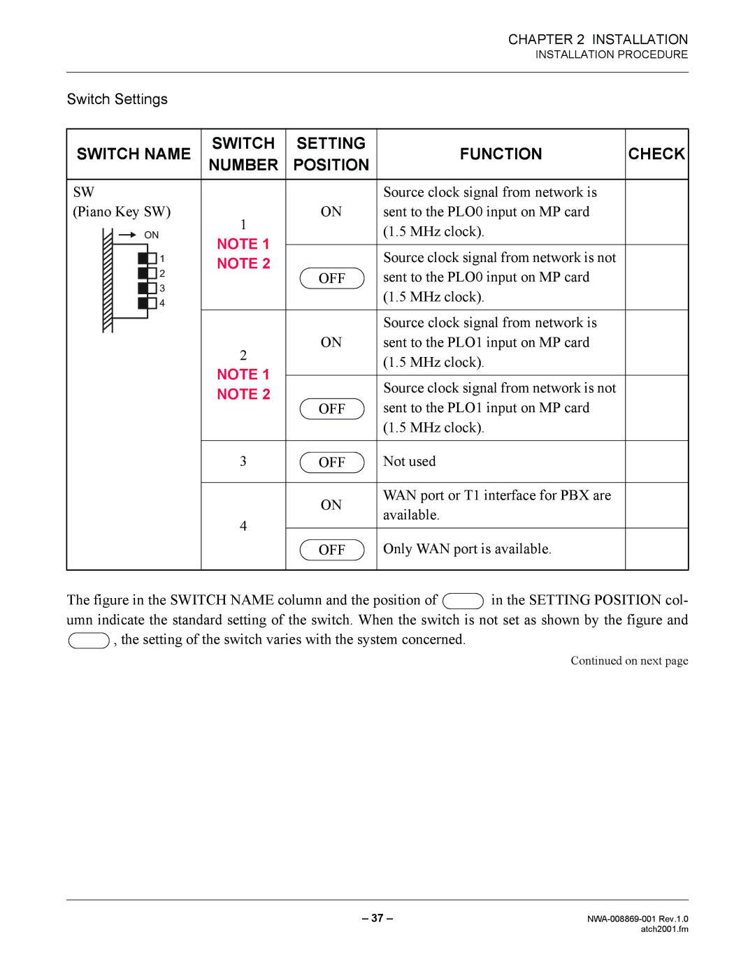
Switch Settings
SWITCH NAME | SWITCH | SETTING | FUNCTION | CHECK | |||||
NUMBER | POSITION | ||||||||
|
|
|
|
|
|
|
|
|
|
SW |
|
| Source clock signal from network is |
| |||||
(Piano Key SW) | 1 | ON | sent to the PLO0 input on MP card |
| |||||
|
|
| ON |
| (1.5 MHz clock). |
| |||
|
|
|
|
| |||||
|
|
| NOTE 1 |
|
| ||||
|
|
|
|
|
|
|
|
| |
|
|
|
|
|
|
| Source clock signal from network is not |
| |
|
|
|
|
| 1 | NOTE 2 |
|
| |
|
|
|
|
| 2 | OFF | sent to the PLO0 input on MP card |
| |
|
|
|
|
|
|
| |||
|
|
| 3 |
|
| (1.5 MHz clock). |
| ||
|
|
|
|
|
|
|
| ||
|
|
|
|
| 4 |
|
|
| |
|
|
|
|
|
|
|
| ||
|
|
|
|
|
|
|
|
| |
|
|
|
|
|
|
|
| Source clock signal from network is |
|
|
|
|
|
|
| 2 | ON | sent to the PLO1 input on MP card |
|
|
|
|
|
|
|
| (1.5 MHz clock). |
| |
|
|
|
|
|
| NOTE 1 |
|
| |
|
|
|
|
|
|
|
|
| |
|
|
|
|
|
|
| Source clock signal from network is not |
| |
|
|
|
|
|
| NOTE 2 |
|
| |
|
|
|
|
|
| OFF | sent to the PLO1 input on MP card |
| |
|
|
|
|
|
|
|
| ||
|
|
|
|
|
|
|
| (1.5 MHz clock). |
|
|
|
|
|
|
|
|
|
|
|
|
|
|
|
|
| 3 | OFF | Not used |
|
|
|
|
|
|
|
|
|
|
|
|
|
|
|
|
|
| ON | WAN port or T1 interface for PBX are |
|
|
|
|
|
|
|
| available. |
| |
|
|
|
|
|
| 4 |
|
| |
|
|
|
|
|
|
|
|
| |
|
|
|
|
|
| OFF | Only WAN port is available. |
| |
|
|
|
|
|
|
|
| ||
|
|
|
|
|
|
|
|
|
|
The figure in the SWITCH NAME column and the position of  in the SETTING POSITION col- umn indicate the standard setting of the switch. When the switch is not set as shown by the figure and
  , the setting of the switch varies with the system concerned.
Continued on next page
– 37 – | |
| atch2001.fm |