CHAPTER 2 INSTALLATION
INSTALLATION PROCEDURE
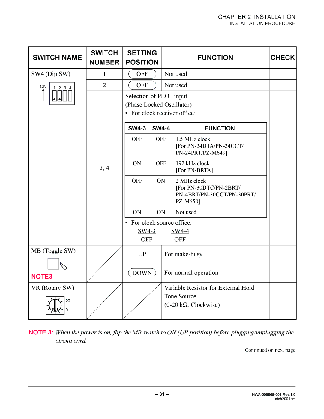
SWITCH NAME | SWITCH | SETTING | FUNCTION | CHECK | ||||
NUMBER | POSITION | |||||||
SW4 (Dip SW) | 1 | OFF | Not used |
| ||||
ON | 1 | 2 | 3 | 4 | 2 | OFF | Not used |
|
|
|
|
|
| ||||
Selection of PLO1 input (Phase Locked Oscillator)
• For clock receiver office:
| FUNCTION | ||
|
|
|
|
| OFF | OFF | 1.5 MHz clock |
|
|
| [For |
|
|
| |
|
|
|
|
3, 4 | ON | OFF | 192 kHz clock |
|
| [For | |
|
|
| |
|
|
|
|
| OFF | ON | 2 MHz clock |
|
|
| [For |
|
|
| |
|
|
| |
|
|
|
|
| ON | ON | Not used |
|
|
|
|
•For clock source office:
OFF OFF
MB (Toggle SW) | UP | For |
|
NOTE3 | DOWN | For normal operation |
|
| |
VR (Rotary SW) |
| Variable Resistor for External Hold |
20 |
| Tone Source |
| ||
0 |
| |
|
|
NOTE 3: When the power is on, flip the MB switch to ON (UP position) before plugging/unplugging the circuit card.
Continued on next page
– 31 – | |
| atch2001.fm |