CHAPTER 2 INSTALLATION
INSTALLATION PROCEDURE
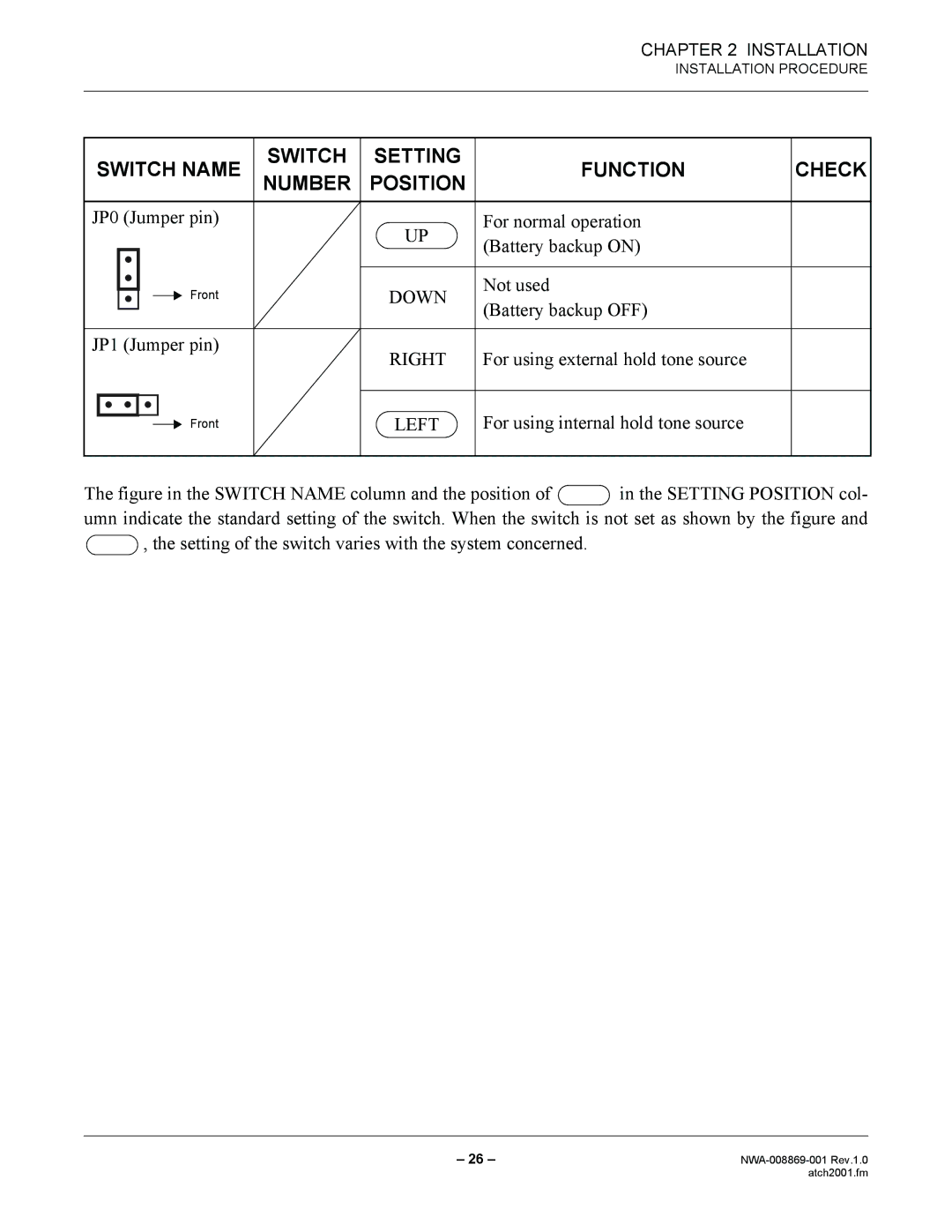
SWITCH NAME | SWITCH | SETTING | FUNCTION | CHECK | ||
NUMBER | POSITION | |||||
|
|
|
|
|
|
|
JP0 (Jumper pin) |
| UP | For normal operation |
| ||
|
|
|
| (Battery backup ON) |
| |
|
|
|
|
|
| |
Front | DOWN | Not used | |
(Battery backup OFF) | |||
|
| ||
JP1 (Jumper pin) | RIGHT | For using external hold tone source | |
| |||
Front | LEFT | For using internal hold tone source |
The figure in the SWITCH NAME column and the position of  in the SETTING POSITION col- umn indicate the standard setting of the switch. When the switch is not set as shown by the figure and
  , the setting of the switch varies with the system concerned.
– 26 – | |
| atch2001.fm |