CHAPTER 2 INSTALLATION
INSTALLATION PROCEDURE
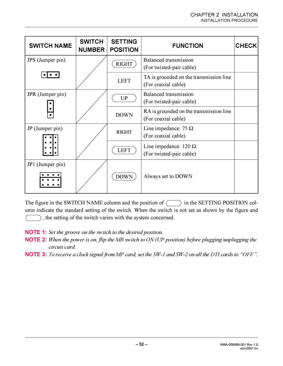
SWITCH NAME | SWITCH | SETTING | FUNCTION | CHECK |
NUMBER | POSITION | |||
JPS (Jumper pin) |
| RIGHT | Balanced transmission |
|
|
| (For |
| |
|
|
|
| |
|
| LEFT | TA is grounded on the transmission line |
|
|
| (For coaxial cable) |
| |
|
|
|
| |
JPR (Jumper pin) |
| UP | Balanced transmission |
|
|
| (For |
| |
|
|
|
| |
|
| DOWN | RA is grounded on the transmission line |
|
|
| (For coaxial cable) |
| |
|
|
|
| |
JP (Jumper pin) |
| RIGHT | Line impedance: 75 Ω |
|
|
| (For coaxial cable) |
| |
|
|
|
| |
|
| LEFT | Line impedance: 120 Ω |
|
|
| (For |
| |
|
|
|
| |
JP1 (Jumper pin) |
|
|
|
|
|
| DOWN | Always set to DOWN |
|
The figure in the SWITCH NAME column and the position of  in the SETTING POSITION col- umn indicate the standard setting of the switch. When the switch is not set as shown by the figure and
  , the setting of the switch varies with the system concerned.
NOTE 1: Set the groove on the switch to the desired position.
NOTE 2: When the power is on, flip the MB switch to ON (UP position) before plugging/unplugging the circuit card.
NOTE 3: To receive a clock signal from MP card, set the
– 52 – | |
| atch2001.fm |