MN101C77C/F77G LSI User’s Manual
Page
Page
Main text Key information
Precautions and warnings
Subtitle Sub-subtitle
Summary
„Finding Desired Information
Page
Page
Contents
Chapter
Chapter Ports
Chapter Prescaler
Chapter Bit Timer
Chapter Watchdog Timer
Serial Interface
Automatic Transfer Controller
Chapter Appendices
18-4 Reprogramming Flow
Page
Chapter Overview
Product Summary
Overview
Overview
Product Summary
KB Flash version 128 KB
Hardware Functions
CPU Core MN101C Core
KB Flash version 6 KB
Timer 1 8-Bit timer for general use
Timers Timers 6 can operate independently
Timer 0 8-Bit timer for general use
External interrupts with/without noise filter
‰ Time base timer
Timer 4 8-Bit timer for general use or Uart baud rate timer
Timer 5 8-Bit timer for general use or Uart baud rate timer
Timer 7 16-Bit timer for general use
Full-Duplex Uart Baud rate timer Timer
Watchdog timer
Remote control output
Buzzer output
‰ Single master IIC
LED driver Pins Port Ports
Special pins Pins
Serial interface 4 Slave IIC ‰ IIC slave serial interface
Overview
Pin Configuration
Pin Description
Pin Specification
Pin Functions
3 Pin Function Summary 1/6
4 Pin Function Summary 2/6
5 Pin Function Summary 3/6
6 Pin Function Summary 4/6
7 Pin Function Summary 5/6
8 Pin Function Summary 6/6
KEY1
Block Diagram
Block Diagram
To Vss
Electrical Characteristics
Absolute Maximum Ratings *2,*3 voltages referenced
1 Crystal Oscillator
MIN TYP
Clock duty rate should be 45% to 55%
MIN TYP MAX
Twh1 Twl1 Twr1 Twf1 Twc1
Twh2 Twl2 Twr2 Twf2 Twc2
Characteristics
5 AC Zero-Cross Detector
VDD=3.3 V,V IN=V SS
Pin 7 P80 to P87 Input high voltage
Converter Characteristics *2
LSB
Resolution *1 Bits Reference voltage low level
Precautions
General Usage
Unused Pins
1 Unused Pins only for input
3 Unused I/O pins high impedance output at reset
Power Supply
Reset Input Voltage Reset pin low level Time
Power Supply Circuit
6 An Example for Emitter follower type Power Supply Circuit
Package Dimension
Package Code LQFP064-P-1414
Package Code TQFP064-P-1010C
Chapter CPU Basics
CPU Basics
1 Block Diagram and Function
Readable / Writable Part of bit is only readable
CPU Control Registers
2 CPU Control Registers
2 Instruction Execution Controller Configuration
Instruction Execution Controller
Pipeline Process
Registers for Address
DW1
Registers for Data
DW0
Processor Status Word
3 Processor Status WordPSW
3 Interrupt Mask Level and Interrupt Acceptance
Addressing Modes
4 Addressing Modes
PSW
Memory Space
Memory Mode
1 Memory Mode Setup
Single-chip Mode
2. Internal ROM / Internal RAM
Special Function Registers
3 Register Map
Bus Interface
Bus Controller
Control Registers
2 Memory Control Register Memctr x03F01 R/W
„Memory Area Control Register Areactr
3 Memory Area Control Register Areactr x03F03, R/W
„Bus Mode Control Register CSMDn
4 Bus Mode Control Register CSMDn x03F05 to x03F09, R/W
Standby Function
1 Transition Between Operation Modes
II 20 Standby Functions
CPU Mode Control Register
2 Operating Mode and Clock Oscillation Cpum x3F00, R/W
Transition between Slow and Normal
Transition to Standby Modes
Processing inside parentheses is handled by hardware
NOP
Clock Switching
Oscmd
CPU
Address Range
Bank Setting
Bank Function
Bank area Address range DBA1 DBA0
Dbnkr
„Bank Register for Source Address
Sbnkr
„Single Chip Mode
Bank Memory Space
ROM Correction
Correction Sequence
ROM Correction
ROM Correction Control Register
Rcctr
„ROM Correction Address 1 Setting Register RC1AP
RC2APH
„ROM Correction Address 2 Setting Register RC2AP
Correspondence
ROM Correction Setup Example
12 Initial Routine for ROM Correction
06BB FF
RC0VL, RC0VH
RC0VL = xB4 RC0VH =
RC1VH =
Corrected at second to the ROM correction address
RC1VL = xBC
Reset
Reset operation
2 Reset Released Sequence
Dlyctr
Oscillation Stabilization Wait time
Nrst Stop
Wdctr
„Oscillation Stabilization Wait Time Control Register
Register Protection
Setting of the Register Protection Function
Rewrite Procedure
Loop MOV
Chapter Interrupts
III 2 Overview
Functions
Interrupt Functions
PSW
CPU core
Operation
RTI
2 Interrupt Vector Address and Interrupt Group
3 Interrupt Priority Outline
Level judgement. Accepted if Ilim
Generated interrupt level IL
Interrupts
PC bits 8-1 → SP+1
Contents of the PSW are saved to the stack
PC bits 16-9 → SP+2
PSW →
Maskable Interrupt
6 Processing Sequence for Maskable Interrupts
III 12 Overview
7 Processing Sequence with Multiple Interrupts Enabled
Interrupt flag setup procedure
Interrupt Flag Setup
Interrupt request flag IR setup by the software
1 Interrupt Control Registers
Control Registers
Registers List
Interrupt Control Registers
1 Non-Maskable Interrupt Control Register NMICRx03FE1, R/W
IRQ0ICR REDG0 IRQ0IE IRQ0IR
LV1
3 External Interrupt 1 Control Register IRQ1ICR x03FE3, R/W
IRQ2ICR REDG2 IRQ2IE IRQ2IR
IRQ2 LV1 LV0
5 External Interrupt 3 Control Register IRQ3ICR x03FE5, R/W
IRQ3ICR REDG3 IRQ3IE IRQ3IR
6 External Interrupt 4 Control Register IRQ4ICR x03FE6, R/W
IRQ4ICR REDG4 IRQ4IE IRQ4IR
TM0ICR TM0IE TM0IR LV1
TM0
TM1ICR TM1IE TM1IR LV1
TM1
TM4ICR TM4IE TM4IR LV1
TM4
TM5ICR TM5IE TM5IR
TM5
TM6ICR TM6IE TM6IR LV1
TM6
15 Time Base Interrupt Control Register Tbicr x03FF0, R/W
Tbicr Tbie Tbir LV1
TM7ICR TM7IE TM7IR LV1
TM7
T7OC2IR
T7OC2IE
SC0RIR
SC0RIE SC0R SC0R LV1 LV0
SC0TIR
SC0TIE SC0T SC0T LV1 LV0
SC1RIR
SC1RIE SC1R SC1R LV1 LV0
SC1TIR
SC1TIE SC1T SC1T LV1 LV0
SC3ICR SC3IE SC3IR LV1 LV0
SC3
SC4ICR SC4IE SC4IR LV1 LV0
SC4
Adicr Adie Adir
ATC1
ATC1IR
ATC1IE
External Interrupts
1 External Interrupt Functions
External Interrupts
P23/IRQ3 Noise filter3 Polarity Inversion Edge detection
External Interrupt 4 Interface Block Diagram
3 External Interrupt 4 Interface Block Diagram
2 External Interrupt Control Register
Readable / Writable
NF1EN
NFCTR0 P21IM
NF0EN
5 Noise Filter Control Register 1 NFCTR1 x03F8D, R/W
6 Both Edges Interrupt Control Register Edgdt x03F8F, R/W
Port 6 Key Interrupt Control Register P6IMD
7 Port 6 Key Interrupt Control Register P6IMD x03F3E, R/W
Rising edge as the active edge for interrupts
Programmable Active Edge Interrupt
REDG4
IRQ4IE
Both Edges Interrupt
IRQ2IE
Key Input Interrupt
IRQ4SEL
External interrupt 4 source to the port 6 key
4 Sampling Cycle / Time of Noise Remove Function
Noise Filter
3 Noise Remove Function
8 Noise Remove Function Operation
NF0EN
REDG0
Interrupt active edge to the rising edge
IRQ0IE
AC Zero-Cross Detector
9 AC Line Waveform and IRQ1 Generation Timing
IRQ1IE
Page
Chapter Ports
1 I/O Port Diagram
1 I/O Port Functions
Port Status at Reset
1 I/O Port Status at Reset Single chip mode
2 I/O Port Control Registers List 1/2
3 I/O Port Control Registers List 2/2
Port
Description
Registers
P0IN P0DIR
2 Block diagram P00
4 Block diagram P02
6 Block Diagram P04
8 Block Diagram P06
IV 12 Port
Port 1 input register P1IN x03F21, R
Port 1 output mode register P1OMD X03F2F, R/W
P10 Output Control register P1TCNT X03F7E, R/W
4 Block Diagram P10, P12, P14
Port 2 IV
Port 2 input registerP2IN x02F22, R
2 Block Diagram P20, P22 to P24
4 Block Diagram P27
Port 5 IV
Port 5 input register P5IN x03F25, R
2 Block Diagram P50
4 Block Diagram P52
6 Block Diagram P54
IV 26 Port
Port 6 output register P6OUT x03F16, R/W
Port 6 Synchronous Output Control Register P6SYOX03F1E, R/W
3 Block Diagram P60 to P67
IV 30 Port
Port 7 output register P7OUT x03F17, R/W
2 Port 7 Registers 2/2
Block Diagram P70
5 Block Diagram P72
7 Block Diagram P74
9 Block Diagram P76, P77
8Port
Port 8 output register P8OUT x03F18, R/W
Port 8 LED Control register P8LED x03F1D, R/W
3 Block Diagram P80 to P87
9Port a
Port a output register Paout X03F1A, R/W
Port a Input control register Paimd X03F3C, R/W
3 Block Diagram PA0 to PA1
10-1 Real Time Output Control Registers
Real Time Output Control Port
10-1 shows the real time output control register of port
IV 46 Real Time Output Control Port
10-1 Real Time Output Control Timing
11-1 Synchronous Output Control Block Diagram
Synchronous output Port
11-1 shows the synchronous output control registers of port
11-1 Synchronous Output Control Registers
11-2 Synchronous Output Event
11-2 Synchronous Output Timing by Event Generation IRQ2
Setup Example
IRQ2
Chapter Prescaler
Prescaler
Peripheral Functions
1 Peripheral Functions Used with Prescaler Output
Block Diagram
1 Prescaler Control Registers
Control Register
1 shows registers to control prescaler
1 Prescaler Control Register Pscmd x03F6F, R/W
2 Timer 0 Prescaler Selection Register CK0MD x03F56, R/W
„Timer 1 prescaler selection register CK1MD
„Timer 4 Prescaler Selection Register CK4MD
„Timer 5 Prescaler Selection Register CK5MD
„Serial Interface 1 Transfer Clock Selection Register SC1CKS
„Serial Interface 3 Transfer Clock Selection Register SC3CKS
CK1MD
Operation
CK0MD
CK4MD
Pscmd to
TM0BAS
Pscen
Chapter Bit Timers
Functions
1 shows functions of each timer
1 Timer Functions
TM0IRQ TM1IRQ TM4IRQ TM5IRQ
„Timers
TM1MD
Diagram
„Timer
Block Diagram
Rmctr
„Remote Control Carrier Output Block Diagram
MUX
1 8-bit Timer Control Registers
TM4BC
„Timer 4 Compare Register TM4OC
Programmable Timer Registers
„Timer 1 Compare Register TM1OC
„Timer 5 Compare Register TM5OC
„Timer 5 Binary Counter TM5BC
„Timer 1 Binary Counter TM1BC
„Timer 4 Binary Counter TM4BC
TM0EN
Timer Mode Registers
TM0MD
TM0PWM
TM1EN
„Timer 1 Mode Register TM1MD
TM1MD
TM1CAS
TM4EN
„Timer 4 Mode Register TM4MD
TM4MD
TM4MOD
TM5EN
„Timer 5 Mode Register TM5MD
TM5MD
TM5MOD
„Remote Control Carrier Output Control Register Rmctr
Rmbtms
8-bit Timer Count
1 Clock Source Timers 0, 1, 4 and 5 at Timer Operation
1 Count Timing of Timer Operation Timers 0, 1, 4
TM0MOD
TM0EN
TM0PWM
TM0IE
8-bit Event Count
1 Event Count Input Clock
2 Count Timing of Synchronous TMnIO Input Timers 0, 1, 4
P1DIR1
TM0ICR
VI 22 8-bit Event Count
„Count Timing of Timer Pulse Output Timers 0, 1, 4
8-bit Timer Pulse Output
1 Timer Pulse Output Pins
P1OMD0
P1DIR0
Bit Timers
8-bit PWM Output
1 Output Pins of PWM Output
„Count Timing of PWM Output at normal Timers 0, 4
2 Count Timing of PWM Output when compare register is
P1DIR x3F31 Control register P1DIR to 1 for the output Bp0
PWM operation
TM0EN
„Count Timing of Synchronous Output Timer 1, Timer
8-bit Timer Synchronous Output
1 Synchronous Output Port Timer 1, Timer
TM1BAS
TM1EN
TM1CAS
Pscmd x3F6F Prescaler counting Bp0
VI 32 Synchronous Output
Serial Interface Transfer Clock Output
1 Timer for Serial Interface Transfer Clock
„Timing of Serial Interface Transfer Clock Timers 4
TM4MOD
TM4EN
TM4PWM
TM4BAS
Bit Timers
1 Simple Pulse Width Measurement Able Pins Timers 0, 4
Simple Pulse Width Measurement
IRQ2ICR
REDG2
VI 38 Simple Pulse Width Measurement
10-1 Timer Functions at Cascade Connection
Cascade Connection
VI 40 Cascade Connection
Connection
Timer 1 mode register to 0 to stop timer 0
TM1MD x3F55 Timer 1 counting Bp3
TM1IE
Remote Control Carrier Output
11-1 Duty Cycle of Remote Control Carrier Output Signal
RMDTY0
Rmoen
Rmbtms
TM0RM
Normal timer operation
Page
Chapter Bit Timer
1 shows the functions of timer
1 16-bit Timer Functions
1 Timer 7 Block Diagram
„Timer 7 Block Diagram
Readable/Writable Readable only
1 shows the registers that control timer
1 16-bit Timer Control Registers
1 Timer 7 Compare Register 1 Lower 8 bits TM7OC1L x03F72, R
„Timer 7 Compare Register 2 TM7OC2
5 Timer 7 Preset Register 1 Lower 8 bits TM7PR1L x03F74, R/W
„Timer 7 Preset Register 2 TM7PR2
9 Timer 7 Binary Counter Lower 8 bits TM7BCL x03F70, R
TM7CL
TM7CK0
TM7EN
„Timer 7 Mode Register 2 TM7MD2
16-bit Timer Count
2 Clock Source at Timer OperationTimer
2 shows the clock source that can be selected
VII 12 16-bit Timer Count
Compare match as a binary counter clear
TM7EN
TM7BCR
TM7IE
VII 14 16-bit Timer Count
1 Count Timing TM7IO Input Timer
16-bit Event Count
2 Count Timing of Synchronous TM7IO Input Timer
Compare match as a clear source of binary
Counter
VII 18 16-bit Event Count
16-bit Timer Pulse Output
1 Timer Pulse Output Pin
„Count Timing of Timer Pulse Output Timer
1 Count Timing of Timer Pulse Output Timer
Source of a binary counter
TM7PWM
Pulse output
TM7CL
1 PWM Output Pin
„Count Timing of Standard PWM Output at NormalTimer
16-bit Standard PWM Output
PWM output shows H , when TM7EN flag is stopped at
4 Output Waveform of TM7IO Output Pin
VII 26 16-bit Standard PWM Output
16-bit High Precision PWM Output
Cycle/Duty can be changed consecutively
VII 28 16-bit High Precision PWM Output
P1OMD4
Also, set the T7PWMSL flag to 1 to select
VII 30 16-bit High Precision PWM Output
16-bit Timer Synchronous Output
1 Count Timing of Synchronous Output Timer
Source of the binary counter
TM7EN
16-bit Timer Capture
Capture Trigger
3-4. Programmable active Edge Interrupt
VII 36 16-bit Timer Capture
External interrupt IRQ 0 input Pulse width to be measured
3 Pulse Width Measurement of External Interrupt
T7ICEDG
T7ICEN
Chapter Time Base Timer Bit Free-running Timer
1 Clock Source and Generation Cycle
Tbirq TM6IRQ
„Timer 6, Time Base Timer Block Diagram
1 Block Diagram Timer 6, Time Base Timer
1 shows the registers that control timer 6, time base timer
Control Registers
TM6OC
„Timer 6 Compare Register TM6OC
TM6BC
Tbclr
TM6CLRS
TM6MD
TM6CKS0
8-bit Free-running Timer
1 Clock Source at Timer Operation Timer
Bp1 Hz1 s
2 1 minute-timer, 1 second-timer Setup Timer
TM6BC
2 Count Timing of Timer Operation Timer
Set the TM6IE flag of the TM6ICR register to
TM6ICR x3FEF Bp1
TM6IE
Above steps 1, 2 can be set at once
Viii
Time Base Timer
1 Time Base Timer Interrupt Generation Cycle
1 Count Timing of Timer Operation Time Base Timer
Tbie
Tbicr
If the interrupt request flag had already been
Chapter Watchdog Timer
„Watchdog Timer Block Diagram
1 Block Diagram Watchdog Timer
1 Watchdog Timer Control Register Wdctr x03F02, R/W
Watchdog timer cannot stop, once it starts operation
1 Watchdog Timer Period
2 The Lowest Value for Watchdog Timer Clear
IX 6 Operation
Setup Example
Maskable interrupt control register Nmicr is
On the interrupt service routine,
Tbnz Nmicr WDIR, Wdpro
Manage the suitable execution
Buzzer
„Buzzer Block Diagram
1 Block Diagram Buzzer
„Oscillation Stabilization Wait Timer Control Register
1 Buzzer Output Frequency
BUZS2 BUZS1 BUZS0
Operation X
Page
Serial Interface 0,1
1 Serial Interface 0, 1 used pins
P01/SBI1A/RXD1A P74/SBI1B/RXD1B P02/SBT1A P75/SBT1B
1 shows functions of serial interface 0
1 Serial Interface 0, 1 Functions
1 Serial Interface 0 Block Diagram
„Serial Interface 0 Block Diagram
2 Serial Interface 1 Block Diagram
„Serial Interface 1 Block Diagram
Readable / Writable Readable only
1 shows registers to control serial interface 0
1 Serial Interface 0, 1 Control Registers
Serial Interface 0 Data Buffer Registers
„Serial Interface 0 Transmissin Data Buffer TXBUF0
Serial Interface 0 Mode Registers
„Serial Interface 0 Mode Register 0 SC0MD0
„Serial Interface 0 Mode Register 1 SC0MD1
4 Serial Interface 0 Mode Register 1 SC0MD1 x03F93, R/W
„Serial Interface 0 Mode Register 2 SC0MD2
SC0BRKF flag is only for reading
„Serial Interface 0 Mode Register 3 SC0MD3
All flags are only for reading
„Serial Interface 0 Port Control Register SC0ODC
„Serial Interface 0 Transfer Clock Selection Register SC0CKS
Serial Interface 1 Data Buffer Registers
„Serial Interface 1 Transmissin Data Buffer TXBUF1
Serial Interface 1 Mode Registers
„Serial Interface1 Mode Register 0 SC1MD0
„Serial Interface 1 Mode Register 1 SC1MD1
12 Serial Interface 1 Mode Register 1 SC1MD1 x03F9B, R/W
„Serial Interface 1 Mode Register 2 SC1MD2
SC1BRKF flag is only for reading
„Serial Interface 1 Mode Register 3 SC1MD3
14 Serial Interface 1 Mode Register 3 SC1MD3 x03F9D, R
„Serial Interface 1 Port Control Register SC1ODC
„Serial Interface1 Transfer Clock Selection Register SC1CKS
SC1CKS
Clock Synchronous Serial Interface
1 Synchronous Serial Interface Activation Factor
XI 22 Operation
TXBUFn
2 Transmission Data Output Edge and Received Data Input Edge
3 Synchronous Serial Interface Internal Clock Source
XI 26 Operation
4 Last Bit Data Length of Transfer Data
5 Other Control Flag
„Trasnmission Timing
Tmax=1.5 T Tmax=2 T
9 Reception Timing rising edge, start condition is enabled
„Reception Timing
11 Reception Timing falling edge, start condition is enabled
XI 32 Operation
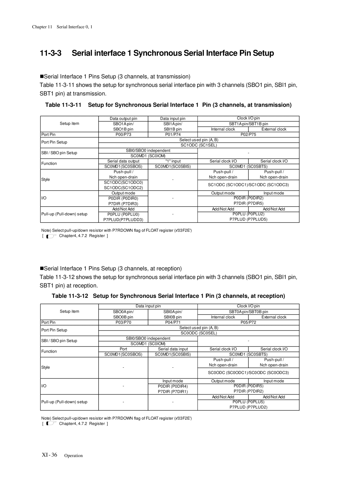
Serial interface 0 Synchronous Serial Interface Pin Setup
XI 34 Operation
P7DIR P7DIR0 P7DIR P7DIR7
Serial interface 1 Synchronous Serial Interface Pin Setup
SC0ODC SC1SEL
XI 38 Operation
MSB
XI 40 Operation
Interrupt Flag Setup
Uart Serial Interface
17 Uart Serial Interface Functions
Serial Interface 0
15 shows the data format at Uart communication
18 Uart Serial Interface Transmission / Reception Data
19 Uart Serial Interface Frame Mode
20 Parity Bit of Uart Serial Interface
21 Reception Error Source of Uart Serial Interface
Serial Interface 0
XI 48 Operation
16 Transmission Timing parity bit is enabled
„Transmission Timing
18 Reception Timing parity bit is enabled
22 Uart Serial Interface Transfer Rate Setup Register
23 Uart Serial Interface Transfer Rate Setup Register
24-1 Uart Serial Interface Transfer Rate decimal
9600 19200 28800 31250 38400 MHz Timer
24-2 Uart Serial Interface Transfer Rate decimal
Serial interface 0 Uart Serial Interface Pin Setup
SC0ODC SC0SEL
27 Uart Serial Interface 0 Pin Setup 1 channel, at reception
Serial interface 1 Uart Serial Interface Pin Setup
SC1ODC SC1SEL
31 Uart Serial Interface 1 Pin Setup 1 channel, at reception
33 Uart Interface Transmision Reception Setup
Serial Interface 0
XI 60 Operation
Serial Interface
1 shows the functions of serial interface
1 Serial Interface 3 Functions List
12-1-2 Block Diagram
1 shows the registers to control serial interface
1 Serial Interface 3 Control Registers
Data Register
SC3TRB
Mode Registers
„Serial Interface 3 Mode Register 0 SC3MD0
„Serial Interface 3 Mode Register 1 SC3MD1
3 Serial Interface 3 Mode Register 1 SC3MD1 x03FA9, R/W
„Serial Interface 3 Control Register SC3CTR
„Serial Interface 3 Port Control Register SC3ODC
1 Activation factor of Synchronous Serial Interface
1-1 Transfer Bit Count and First Transfer Bit at MSB first
„Receive Bit Count and First Transfer Bit
2 Synchronous Serial Interface Internal Clock Source
3 Input Edge/Output Edge of Transmission/Received Data
4 Last Bit Data Length of Transmission Data
2 Transmission Timing Falling edge, Enable Start Condition
4 Transmission Timing Rising edge, Enable Start Condition
6 Reception Timing Rising edge, Enable Start Condition
8 Reception Timing Falling edge, Enable Start Condition
XII 18 Operation
SBI3/SBO3
XII 20 Operation
SC3ODCSC3ODC0 SC3ODCSC3ODC1
P5PLUP5PLU1 P5PLUP5PLU2
XII 22 Operation
Function Port Serial data input Serial clock I/O
XII 24 Operation
Interrupt Flag Setup
XII 26 Operation
Single Master IIC Interface
11 IIC Serial Interface Functions
12 Start Condition and Stop Condition
13 ACK Bit Reception Timing after Transmission of 8-Bit Data
Free data format master transmission
Addressing format master transmission
Addressing format master reception
12 IIC Interface Clock Source
16 Master Transmission Timing, -3-17 Master Reception Timing
„Master Transmission Timing
16 Master Transmission Timing
„Master Reception Timing
17 Master Reception Timing
13 Pin Setup 2 channels, at transmission
14 Pin Setup 2 channels, at reception
15 Conditions Single Master IIC Communication Setup
Serial Interface
XII 38 Operation
Is . When SC3ACKO = 1, the reception at
XII 40 Operation
Serial Interface
1 Serial interface 4 Functions List
„Serial interface 4 Block Diagram
SC4STR
1 Serial interface 4 Control Registers
1 Serial interface 4 Reception Data Buffer SC4RXB x03FAD, R
„Serial interface 4 Transmission Data Buffer SC4TXB
I2CAD7 I2CAD6 I2CAD5 I2CAD4 I2CAD3 I2CAD2 I2CAD1 I2CAD0
„Serial interface 4 Addressing Register 0 SC4AD0
„Serial interface 4 Addressing Register 1 SC4AD1
„Serial interface 4 Status Register SC4STR
5 Serial interface 4 Status Register SC4STR x03FAC, R
„Serial interface 4 Port Control Register 0 SC4ODC0
„Serial interface 4 Port Control Register 1 SC4ODC1
Operation Xiii
SC4ODC1
Pin Setup
SC4ODC0
Setup Example of the Slave IIC Serial Interface
Xiii 12 Operation
Automatic Transfer Controller
14-1-1 ATC1
Transfer Modes
1 ATC1 Trigger Factors
„ATC Transfer Modes
„ATC1 Block Diagram
1 ATC1 Block Diagram
1 shows the registers used to control ATC1
1 ATC1 Control Registers
„ATC1 Control Register 0 AT1CNT0
1 ATC1 Control Register 0 AT1CNT0 x03FD0, R/W
„ATC1 Control Register 1 AT1CNT1
„ATC1 Transfer Counter AT1TRC
„ATC1 Memory Pointer 0 AT1MAP0
„ATC1 Memory Pointer 1 AT1MAP1
Basic Operations and Timing
„Data transfer
„Transfer end
„Memory pointer 0 functions
Setting the Memory Address
„Setting the transfer addresses to the memory pointers
„Memory pointer 1 functions
„The transfer data counter AT1TRC
Setting the Data Transfer Count
„Transfer data counter AT1TRC function
„Standard and burst transfers
Setting the Data Transfer Modes
„Data transfer modes
AT1MAP1
Transfer Mode
AT1MAP0
3 Transfer Mode
4 Transfer Mode
5 Transfer Mode
6 Transfer Mode
7 Transfer Mode
8 Transfer Mode
Automatic Transfer Controller
9 Transfer Mode
Automatic Transfer Controller
10 Transfer Mode
Automatic Transfer Controller
11 Transfer Mode
Automatic Transfer Controller
Transfer mode a
12 Transfer Mode a
Transfer Mode B
13 Transfer Mode B
Transfer Mode C
14 Transfer Mode C
Transfer Mode D
15 Transfer Mode D
Transfer Mode E
16 Transfer Mode E
Transfer Mode F
17 Transfer Mode F
AT1ACT
Setup Example
Fmode
AT1EN
Setup Example
Page
Converter
1 shows the A/D converter functions
1 A/D Converter Functions
Hold
1 shows the registers used to control A/D converter
1 A/D Converter Control Registers
Anlade
„A/D Converter Control Register 0 ANCTR0
ANCTR0 ANSH1
ANCTR2 Anst
„A/D Converter Control Register 1 ANCTR1
„A/D Converter Control Register 2 ANCTR2
Anstsel
Data Buffers
ANBUF1
XV 8 Operation
1 Operation of A/D Conversion
2 A/D Conversion Clock and A/D Conversion Cycle
Setup
1 Input Pins of A/D Converter Setup
3 Sampling Time of A/D Conversion and A/D Conversion Time
6 A/D Conversion Starting
4 A/D Ladder Resistor Control
5 A/D Conversion Activation Factor Selection
4 Interrupt Flag Setting
Converter
Padir
Converter
2 A/D Converter Recommended Example
Recommended Connection with A/D Converter
Page
Converter
1 shows the D/A converter functions
1 D/A Converter Functions
Operation XVI
1 D/A Converter Control Registers
Readable/Writable
Control Register Dactr
1 D/A Converter Control Register Dactr x03FBE R/W
Input Data Registers
2 D/A Converter Input Data Register 01 DADR01 x03FBF R/W
Paplud
Page
Appendices
Top view of MBB board
Probe Switches
PRB-MBB101C77-M
OFF OP0 OP1 OP2 OP3 OP4 OP5
PX-CN101-M
MBB board PRB-MBB101∗∗∗-M
PRB-ADP101-64-M
MBB board PRB-MBB101∗∗∗-M
17-1-4PRB-DMY101C77-M
MBB board PRB-MBB101C77-M
17-2 Special Function Registers List
Special Function Registers List
Xvii 8 Special Function Registers List
TM1OC2
Xvii 10 Special Function Registers List
SC0ODC
Xvii 12 Special Function Registers List
Nmicr
Xvii 14 Special Function Registers List
I2CAD7 I2CAD6 I2CAD5 I2CAD4 I2CAD3 I2CAD2 I2CAD1 I2CAD0
Instruction Set
MOV
Instruction Set
D4 sign-extension D7 sign-extension D11 sign-extension
Cbeq
JMP
INC ADD DEC Addw INC2 DEC2 CLR SUB
17-4
Instruction Map
Ver2.12001.03.26
Page
Flash Eeprom
Eeprom
XVIII-2 Overview
1 Memory Map in Internal Flash Eeprom
Differences between Mask ROM version and Eprom version
1 Differences between Mask ROM version and Eprom version
1 Pin Configuration LQFP064-P-1414
Pin Descriptions
Absolute Maximum Ratings*2,*3
Sens
Normal mode fs=fosc/2, Slow mode fs=fx/2
Operating Conditions
DC Characteristics
Reprogramming Flow
1 Reprogramming Flow of Internal Flash Eeprom
Prom writer mode
„Pin Configuration for Socket Adaptor
2 Pin Configuration for Socket Adaptor
Onboard Serial Programming Mode
1 Target Board for programming using the YDC Serial Writer
This section describes each memory space of Flash Eeprom
X06088 to X23FFF This area stores the user program
XVIII-15
3 Target Board for programming using the PanaX Serial Writer
Pull-up resistor value
Maximum output current of pin I OL
Pull-up resistor RupMin X Load capacity
MN101C77C/F77G
Sales Offices