Product Orientation
INVERTER Switch
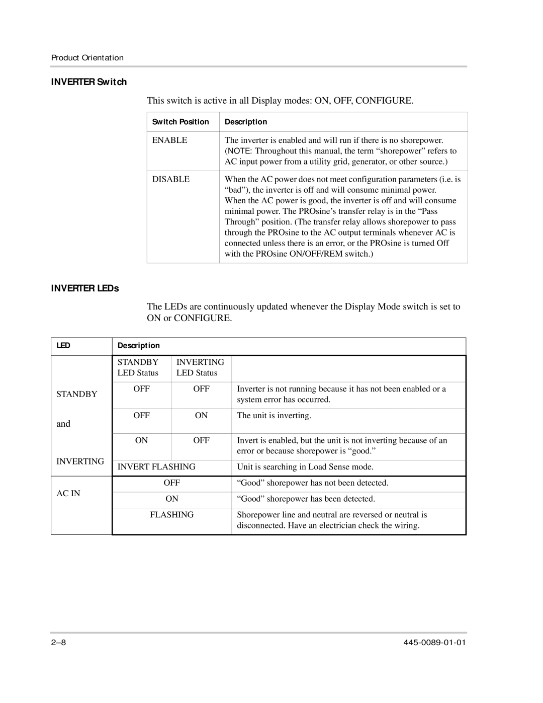
This switch is active in all Display modes: ON, OFF, CONFIGURE.
Switch Position | Description |
|
|
ENABLE | The inverter is enabled and will run if there is no shorepower. |
| (NOTE: Throughout this manual, the term “shorepower” refers to |
| AC input power from a utility grid, generator, or other source.) |
|
|
DISABLE | When the AC power does not meet configuration parameters (i.e. is |
| “bad”), the inverter is off and will consume minimal power. |
| When the AC power is good, the inverter is off and will consume |
| minimal power. The PROsine’s transfer relay is in the “Pass |
| Through” position. (The transfer relay allows shorepower to pass |
| through the PROsine to the AC output terminals whenever AC is |
| connected unless there is an error, or the PROsine is turned Off |
| with the PROsine ON/OFF/REM switch.) |
|
|
INVERTER LEDs
The LEDs are continuously updated whenever the Display Mode switch is set to ON or CONFIGURE.
LED | Description |
|
|
| |
|
|
|
|
|
|
|
| STANDBY |
| INVERTING |
|
|
| LED Status |
| LED Status |
|
|
|
|
|
|
|
STANDBY | OFF |
| OFF | Inverter is not running because it has not been enabled or a | |
|
|
| system error has occurred. | ||
|
|
|
|
| |
|
|
|
|
|
|
and | OFF |
| ON | The unit is inverting. | |
|
|
|
| ||
|
|
|
|
|
|
|
| ON |
| OFF | Invert is enabled, but the unit is not inverting because of an |
INVERTING |
|
|
|
| error or because shorepower is “good.” |
|
|
|
|
| |
| INVERT FLASHING | Unit is searching in Load Sense mode. | |||
|
| ||||
|
|
|
|
| |
AC IN |
|
| OFF | “Good” shorepower has not been detected. | |
|
|
|
|
| |
|
| ON | “Good” shorepower has been detected. | ||
|
|
| |||
|
|
|
| ||
|
| FLASHING | Shorepower line and neutral are reversed or neutral is | ||
|
|
|
|
| disconnected. Have an electrician check the wiring. |
|
|
|
|
|
|