Step 9: Connecting the Battery Temperature Sensor
Mounting to the Side of the Battery Case
To mount the sensor on the battery case
See Figure
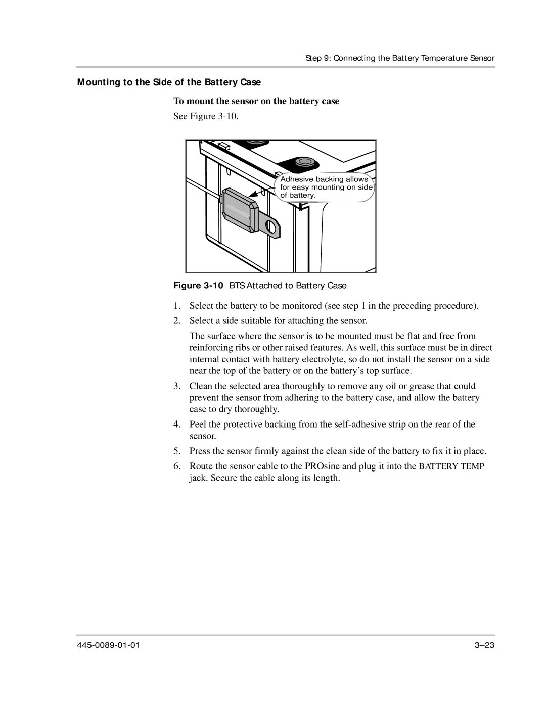
Adhesive![]() backing allows for easy mounting on side of battery.
backing allows for easy mounting on side of battery.
Figure 3-10 BTS Attached to Battery Case
1.Select the battery to be monitored (see step 1 in the preceding procedure).
2.Select a side suitable for attaching the sensor.
The surface where the sensor is to be mounted must be flat and free from reinforcing ribs or other raised features. As well, this surface must be in direct internal contact with battery electrolyte, so do not install the sensor on a side near the top of the battery or on the battery’s top surface.
3.Clean the selected area thoroughly to remove any oil or grease that could prevent the sensor from adhering to the battery case, and allow the battery case to dry thoroughly.
4.Peel the protective backing from the
5.Press the sensor firmly against the clean side of the battery to fix it in place.
6.Route the sensor cable to the PROsine and plug it into the BATTERY TEMP jack. Secure the cable along its length.