Installation
The PROsine is shipped with the screw in the position that enables the automatic bonding system.
•To disable the system, move the screw to the other hole.
•Do not remove the screw from the product: make sure it is always installed in one position or the other, as appropriate for the configuration of the rest of the system.
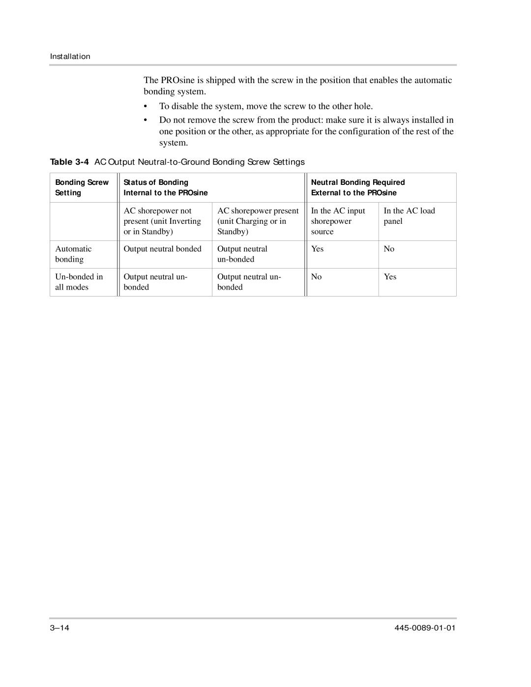
Table 3-4 AC Output Neutral-to-Ground Bonding Screw Settings
Bonding Screw |
| Status of Bonding |
|
| Neutral Bonding Required | |
Setting |
| Internal to the PROsine |
|
| External to the PROsine | |
|
|
|
|
|
|
|
|
| AC shorepower not | AC shorepower present |
| In the AC input | In the AC load |
|
| present (unit Inverting | (unit Charging or in |
| shorepower | panel |
|
| or in Standby) | Standby) |
| source |
|
|
|
|
|
|
|
|
Automatic |
| Output neutral bonded | Output neutral |
| Yes | No |
bonding |
|
|
|
|
| |
|
|
|
|
|
|
|
| Output neutral un- | Output neutral un- |
| No | Yes | |
all modes |
| bonded | bonded |
|
|
|
|
|
|
|
|
|
|