ATM Backplane
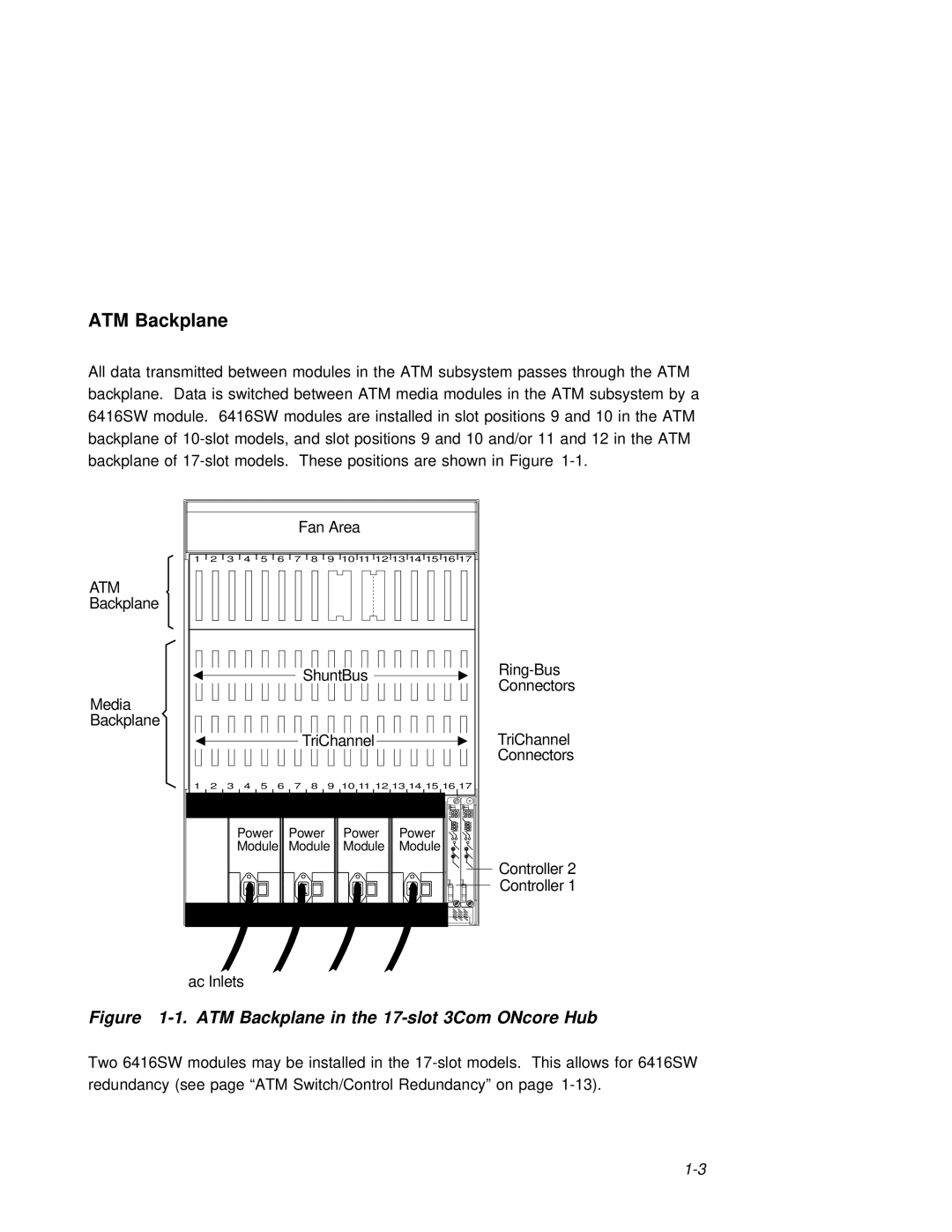
All data | transmitted | between modules in the ATM subsystem passes through the ATM | |||||||||||||
backplane. Data is | switched | between | ATM | media | modules | in | the | ATM | subsystem | by | a | ||||
6416SW module. 6416SW | modules | are | installed | in | slot positions 9 | and | 10 in the | ATM |
| ||||||
backplane | of | models, | and slot | positions | 9 | and 10 and/or 11 and 12 | in | the ATM | |||||||
backplane | of | models. | These | positions are | shown | in | Figure |
|
| ||||||
|
|
|
|
|
| Fan Area |
| |||
1 | 2 | 3 | 4 | 5 | 6 | 7 | 8 | 9 | 10 11 12 13 14 15 16 17 | |
ATM |
|
|
|
|
|
|
|
|
|
|
Backplane |
|
|
|
|
|
|
|
|
|
|
|
|
|
|
|
|
| ShuntBus | |||
|
|
|
|
|
|
| Connectors | |||
|
|
|
|
|
|
|
|
|
| |
Media |
|
|
|
|
|
|
|
|
|
|
Backplane |
|
|
|
|
|
|
|
|
|
|
|
|
|
|
|
|
| TriChannel | TriChannel | ||
|
|
|
|
|
|
|
|
|
| Connectors |
1 | 2 | 3 | 4 | 5 | 6 | 7 | 8 | 9 | 10 11 12 13 14 15 16 17 | |
|
|
| Power |
| Power |
| Power | Power | ||
|
|
| Module | Module | Module | Module | ||||
|
|
|
|
|
|
|
|
|
| Controller 2 |
|
|
|
|
|
|
|
|
|
| Controller 1 |
ac Inlets
Figure 1-1. ATM Backplane in the 17-slot 3Com ONcore Hub
Two 6416SW modules may be installed in the