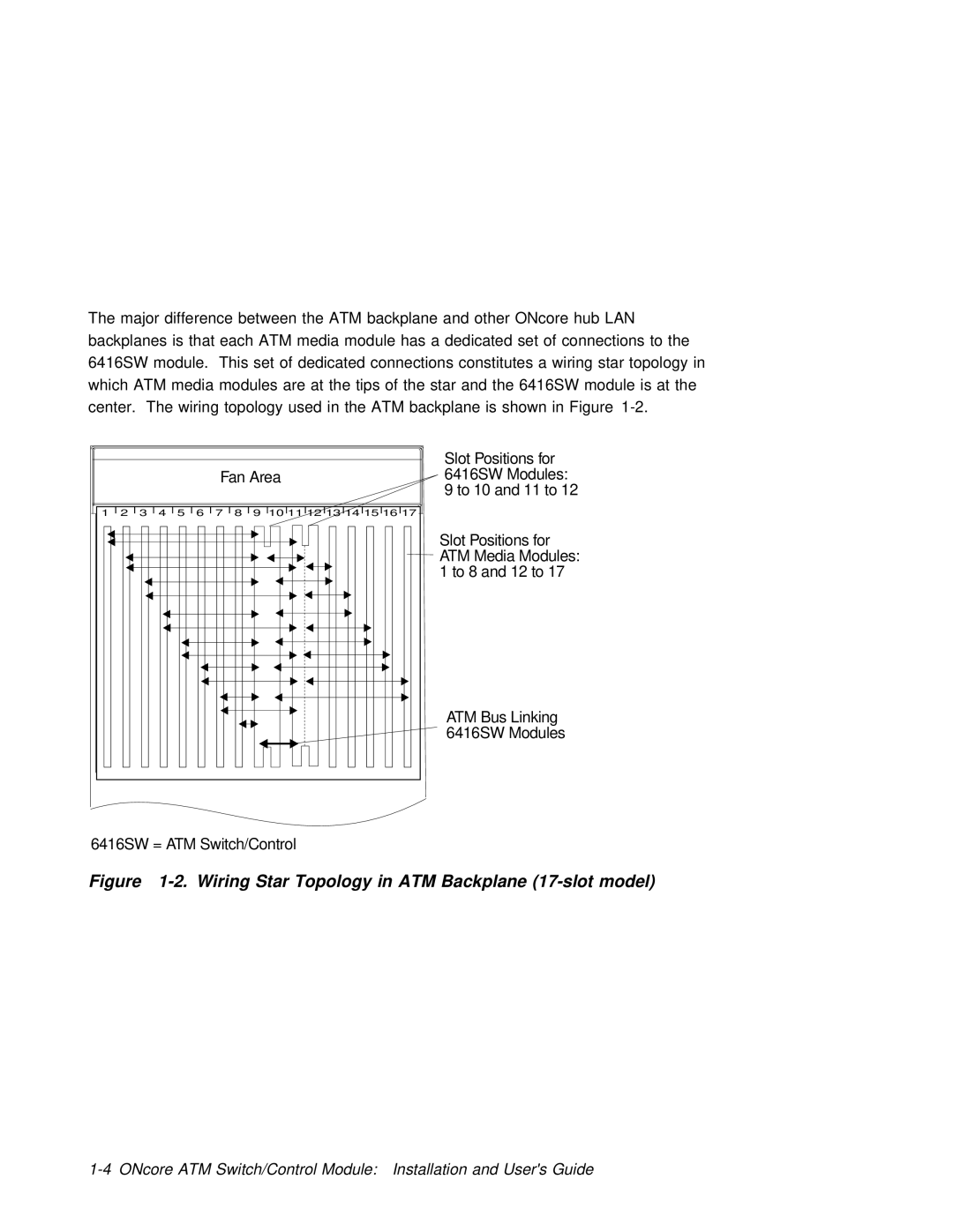
The major difference between the | ATM | backplane and | other | ONcore | hub | LAN |
| |||||||
backplanes is that each ATM | media module has a dedicated set of connections to the | |||||||||||||
6416SW module. This set of | dedicated | connections | constitutes | a | wiring | star topology | in | |||||||
which ATM media modules are | at | the | tips | of | the | star | and | the | 6416SW | module is at | the | |||
center. The wiring topology | used | in | the | ATM | backplane | is | shown | in | Figure |
| ||||
Fan Area
1 | 2 | 3 | 4 | 5 | 6 | 7 | 8 | 9 10 11 12 13 14 15 16 17 |
Slot Positions for 6416SW Modules:
9 to 10 and 11 to 12
Slot Positions for ATM Media Modules: 1 to 8 and 12 to 17
ATM Bus Linking 6416SW Modules
6416SW = ATM Switch/Control