Chapter 3 - Commissioning
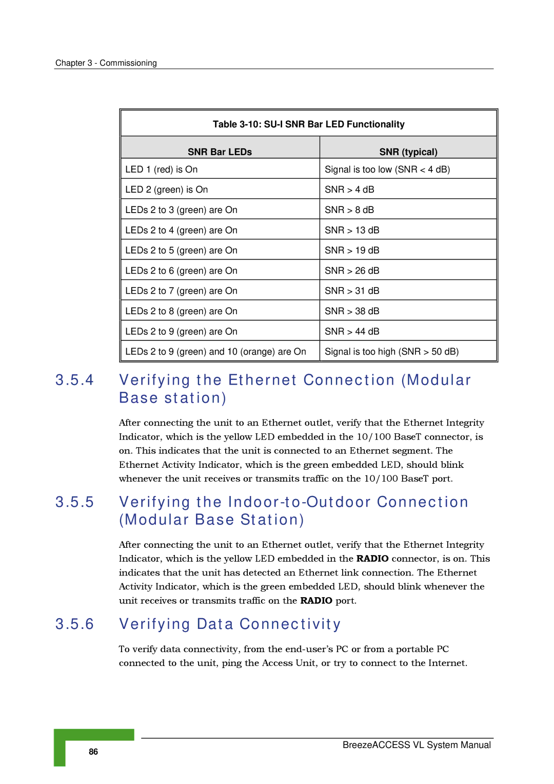
Table 3-10: SU-I SNR Bar LED Functionality
| SNR Bar LEDs | SNR (typical) |
| ||
LED 1 (red) is On | Signal is too low (SNR < 4 dB) | |
|
| |
LED 2 (green) is On | SNR > 4 dB | |
|
| |
LEDs 2 to 3 (green) are On | SNR > 8 dB | |
|
| |
LEDs 2 to 4 (green) are On | SNR > 13 dB | |
|
| |
LEDs 2 to 5 (green) are On | SNR > 19 dB | |
|
| |
LEDs 2 to 6 (green) are On | SNR > 26 dB | |
|
|
|
LEDs 2 to 7 | (green) are On | SNR > 31 dB |
|
|
|
LEDs 2 to 8 | (green) are On | SNR > 38 dB |
|
|
|
LEDs 2 to 9 | (green) are On | SNR > 44 dB |
|
|
|
LEDs 2 to 9 | (green) and 10 (orange) are On | Signal is too high (SNR > 50 dB) |
|
|
|
3.5.4Verifying the Ethernet Connection (Modular Base station)
After connecting the unit to an Ethernet outlet, verify that the Ethernet Integrity Indicator, which is the yellow LED embedded in the 10/100 BaseT connector, is on. This indicates that the unit is connected to an Ethernet segment. The Ethernet Activity Indicator, which is the green embedded LED, should blink whenever the unit receives or transmits traffic on the 10/100 BaseT port.
3.5.5Verifying the
After connecting the unit to an Ethernet outlet, verify that the Ethernet Integrity Indicator, which is the yellow LED embedded in the RADIO connector, is on. This indicates that the unit has detected an Ethernet link connection. The Ethernet Activity Indicator, which is the green embedded LED, should blink whenever the unit receives or transmits traffic on the RADIO port.
3.5.6Verifying Data Connectivity
To verify data connectivity, from the
86