Installing the Modular Base Station Equipment

2.6Installing the Modular Base Station Equipment

The following sections describe the slot assignment for the Base Station chassis, provide illustrated descriptions of the power supply modules and Access Unit network interface modules, and describe how to install the Base Station equipment.

2.6.1BS-SH Slot Assignment

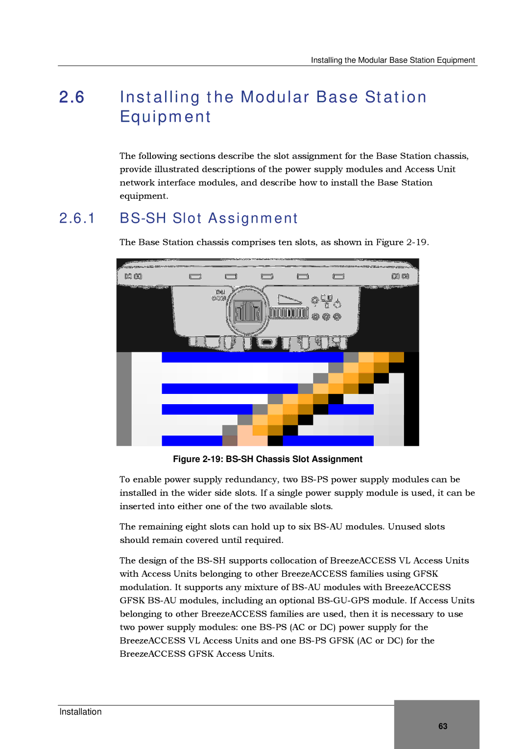
The Base Station chassis comprises ten slots, as shown in Figure 2-19.

Figure 2-19: BS-SH Chassis Slot Assignment

To enable power supply redundancy, two BS-PS power supply modules can be installed in the wider side slots. If a single power supply module is used, it can be inserted into either one of the two available slots.

The remaining eight slots can hold up to six BS-AU modules. Unused slots should remain covered until required.

The design of the BS-SH supports collocation of BreezeACCESS VL Access Units with Access Units belonging to other BreezeACCESS families using GFSK modulation. It supports any mixture of BS-AU modules with BreezeACCESS GFSK BS-AU modules, including an optional BS-GU-GPS module. If Access Units belonging to other BreezeACCESS families are used, then it is necessary to use two power supply modules: one BS-PS (AC or DC) power supply for the BreezeACCESS VL Access Units and one BS-PS GFSK (AC or DC) for the BreezeACCESS GFSK Access Units.

Installation

63

Page 95
Image 95
Alvarion SW VERSION 5.1 system manual Installing the Modular Base Station Equipment, BS-SH Slot Assignment