Chapter 3 - Commissioning
3.5Operation Verification
The following sections describe how to verify the correct functioning of the Outdoor Unit, Indoor Unit, Ethernet connection and data connectivity.
3.5.1Outdoor Unit Verification
To verify the correct operation of the Outdoor Unit, examine the LED indicators located on the bottom panel of the outdoor unit.
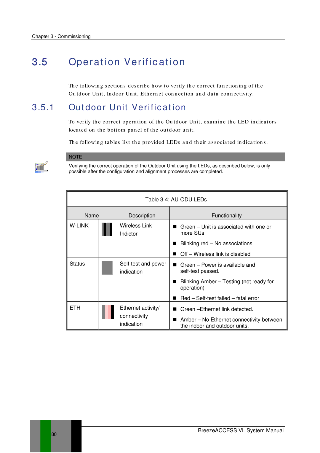
The following tables list the provided LEDs and their associated indications.
NOTE
Verifying the correct operation of the Outdoor Unit using the LEDs, as described below, is only possible after the configuration and alignment processes are completed.
Table 3-4: AU-ODU LEDs
Name | Description | Functionality | ||
|
| Wireless Link | Green – Unit is associated with one or | |
|
| Indictor | more SUs | |
|
|
| Blinking red – No associations | |
|
|
| Off – Wireless link is disabled | |
Status |
| Green – Power is available and | ||
|
| indication | ||
|
|
| Blinking Amber – Testing (not ready for | |
|
|
| operation) | |
|
|
| Red – | |
ETH |
| Ethernet activity/ | Green | |
|
| connectivity | Amber – No Ethernet connectivity between | |
|
| indication | ||
|
| the indoor and outdoor units. | ||
80