Figure 35
BUTTON BORDER menu pages
Note
If DEVICE USED is set to 4 and Base Device Number is 128, the Central Controller recognizes bus devices 128, 129, 130, and 131.
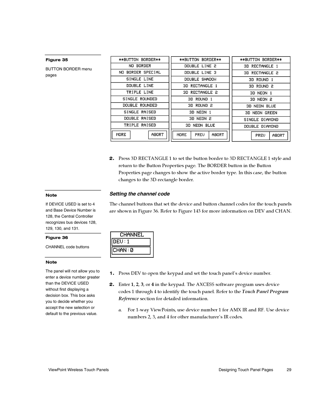
Figure 36
CHANNEL code buttons
Note
The panel will not allow you to enter a device number greater than the DEVICE USED without first displaying a decision box. This box asks you to decide whether you accept the new selection or default to the previous value.
2.Press 3D RECTANGLE 1 to set the button border to 3D RECTANGLE 1 style and return to the Button Properties page. The BORDER button in the Button Properties page changes to show the active border type. In this case, the button changes to the
Setting the channel code
The channel buttons that set the device and button channel codes for the touch panels are shown in Figure 36. Refer to Figure 143 for more information on DEV and CHAN.
1.Press DEV to open the keypad and set the touch panel’s device number.
2.Enter 1, 2, 3, or 4 in the keypad. The AXCESS software program uses device codes 1 through 4 to identify the touch panel. Refer to the Touch Panel Program Reference section for detailed information.
a.For
ViewPoint Wireless Touch Panels | Designing Touch Panel Pages | 29 |