Chapter 4 Installation and Setup
Connecting Cascaded Switches
Note: The information in this section only applies to the P133G2 and P134G2.
Note: The two SFP transceivers on the ends of the cable are identical. Each SFP transceiver can be connected to either an “Up“ or “Down“ port.
To connect cascaded switches
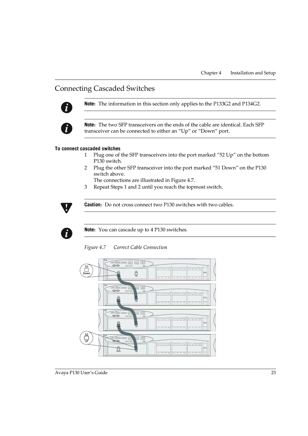
1Plug one of the SFP transceivers into the port marked “52 Up” on the bottom P130 switch.
2Plug the other SFP transceiver into the port marked “51 Down” on the P130 switch above.
The connections are illustrated in Figure 4.7.
3Repeat Steps 1 and 2 until you reach the topmost switch.
Caution: Do not cross connect two P130 switches with two cables.
Note: You can cascade up to 4 P130 switches.
Figure 4.7 | Correct Cable Connection |
|
|
|
|
|
|
|
|
| ||||||||||||||||
| P130 | 51 | 52 | 1 | 2 | 3 | 4 | 5 | 6 | 7 | 8 | 9 | 10 | 11 12 |
|
|
|
|
|
|
|
|
|
|
| |
|
|
|
|
|
|
|
|
|
|
|
|
| ||||||||||||||
|
| EXPANSION |
|
|
|
|
|
|
|
|
|
|
|
|
|
|
|
|
|
|
|
|
|
|
|
|
|
| SLOT |
| 13 |
| 15 | 16 | 17 |
| 19 20 | 21 22 | 23 | 24 |
|
|
|
|
|
|
|
|
|
|
| ||
|
|
|
| 14 | 18 |
|
|
|
|
|
|
|
|
|
|
| ||||||||||
51 |
|
|
| LNK COL Tx | Rx | FDX | 100 |
|
|
|
|
|
| OPR | PWR |
|
|
|
|
|
|
|
|
|
|
|
|
|
|
|
|
|
|
|
|
|
|
|
|
|
|
| LAG |
|
|
| LAG |
|
|
| LAG |
| |
|
|
|
|
|
|
|
|
|
|
|
|
|
|
| 1 | 2 | 3 | 4 | 5 | 6 | 7 | 8 | 9 | 10 | 11 | 12 |
Down |
|
| 51 |
|
|
|
|
| 52 |
|
|
|
|
|
|
|
|
|
|
|
|
|
|
| CONSOLE | |
|
|
|
|
|
|
| Up |
|
|
|
|
|
|
|
|
|
|
|
|
|
|
|
| |||
|
|
| Down |
|
|
|
|
|
|
|
|
|
|
|
|
|
|
|
|
|
|
|
| |||
|
|
|
|
|
|
|
|
|
|
|
|
|
|
| 13 | 14 | 15 | 16 | 17 | 18 | 19 | 20 | 21 | 22 | 23 | 24 |
| P130 | 51 | 52 | 1 | 2 | 3 | 4 | 5 | 6 | 7 | 8 | 9 | 10 | 11 12 |
|
|
|
|
|
|
|
|
|
|
| |
|
| EXPANSION |
|
|
|
|
|
|
|
|
|
|
|
|
|
|
|
|
|
|
|
|
|
|
|
|
|
| SLOT |
| 13 |
| 15 | 16 | 17 |
| 19 20 | 21 22 | 23 | 24 |
|
|
|
|
|
|
|
|
|
|
| ||
|
|
|
| 14 | 18 |
|
|
|
|
|
|
|
|
|
|
| ||||||||||
|
|
|
| LNK COL Tx | Rx | FDX | 100 |
|
|
|
|
|
| OPR | PWR |
|
|
|
|
|
|
|
|
|
|
|
|
|
|
|
|
|
|
|
|
|
|
|
|
|
|
|
| LAG |
|
|
| LAG |
|
|
| LAG |
|
|
|
|
|
|
|
|
|
|
|
|
|
|
|
| 1 | 2 | 3 | 4 | 5 | 6 | 7 | 8 | 9 | 10 | 11 | 12 |
|
|
| 51 |
|
|
|
|
| 52 |
|
|
|
|
|
|
|
|
|
|
|
|
|
|
| CONSOLE | |
|
|
| Down |
|
|
|
| Up |
|
|
|
| 13 | 14 | 15 | 16 | 17 | 18 | 19 | 20 | 21 | 22 | 23 | 24 | ||
|
|
|
|
|
|
|
|
|
|
|
|
|
|
| ||||||||||||
52 | P130 | 51 | 52 | 1 | 2 | 3 | 4 | 5 | 6 | 7 | 8 | 9 | 10 | 11 12 |
|
|
|
|
|
|
|
|
|
|
| |
|
|
|
|
|
|
|
|
|
|
|
|
| ||||||||||||||
|
| EXPANSION |
|
|
|
|
|
|
|
|
|
|
|
|
|
|
|
|
|
|
|
|
|
|
|
|
|
| SLOT |
| 13 |
| 15 | 16 | 17 |
| 19 20 | 21 22 | 23 | 24 |
|
|
|
|
|
|
|
|
|
|
| ||
UP |
|
|
| 14 | 18 |
|
|
|
|
|
|
|
|
|
|
| ||||||||||
|
|
| LNK COL Tx | Rx | FDX | 100 |
|
|
|
|
|
| OPR | PWR |
|
|
|
|
|
|
|
|
|
|
| |
|
|
|
|
|
|
|
|
|
|
|
|
|
|
|
|
| LAG |
|
|
| LAG |
|
|
| LAG |
|
|
|
|
|
|
|
|
|
|
|
|
|
|
|
| 1 | 2 | 3 | 4 | 5 | 6 | 7 | 8 | 9 | 10 | 11 | 12 |
|
|
| 51 |
|
|
|
|
| 52 |
|
|
|
|
|
|
|
|
|
|
|
|
|
|
| CONSOLE | |
|
|
| Down |
|
|
|
| Up |
|
|
|
|
|
|
|
|
|
|
|
|
|
|
|
| ||
|
|
|
|
|
|
|
|
|
|
|
|
|
|
| 13 | 14 | 15 | 16 | 17 | 18 | 19 | 20 | 21 | 22 | 23 | 24 |
Avaya P130 User’s Guide | 23 |