Chapter 4 Installation and Setup
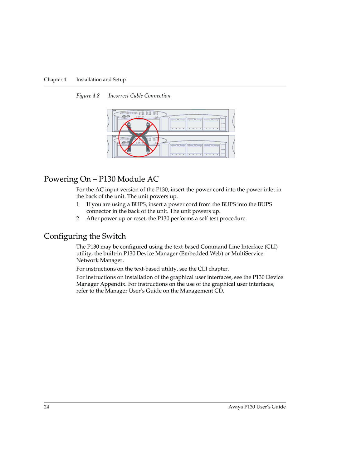
Figure 4.8 Incorrect Cable Connection
P130
51 | 52 |
| 1 | 2 | 3 | 4 | 5 | 6 | 7 | 8 | 9 | 10 | 11 12 |
|
|
|
|
|
|
|
|
|
|
| |
EXPANSION |
|
|
|
|
|
|
|
|
|
|
|
|
|
|
|
|
|
|
|
|
|
|
|
|
|
SLOT |
|
| 13 | 14 | 15 | 16 | 17 | 18 | 19 20 | 21 22 | 23 | 24 |
|
|
|
|
|
|
|
|
|
|
| ||
|
|
|
|
|
|
|
|
|
|
|
|
|
| ||||||||||||
| LNK | COL | Tx | Rx | FDX | 100 |
|
|
|
|
|
| OPR | PWR |
|
|
|
|
|
|
|
|
|
|
|
|
|
|
|
|
|
|
|
|
|
|
|
|
|
|
| LAG |
|
|
| LAG |
|
|
| LAG |
|
|
|
|
|
|
|
|
|
|
|
|
|
|
| 1 | 2 | 3 | 4 | 5 | 6 | 7 | 8 | 9 | 10 | 11 | 12 |
| 51 |
|
|
|
|
|
| 52 |
|
|
|
|
|
|
|
|
|
|
|
|
|
|
| CONSOLE | |
| Down |
|
|
|
|
| Up |
|
|
|
| 13 | 14 | 15 | 16 | 17 | 18 | 19 | 20 | 21 | 22 | 23 | 24 | ||
|
|
|
|
|
|
|
|
|
|
|
|
|
| ||||||||||||
P130 |
|
|
|
|
|
|
|
|
|
|
|
|
|
|
|
|
|
|
|
|
|
|
|
|
|
51 | 52 |
| 1 | 2 | 3 | 4 | 5 | 6 | 7 | 8 | 9 | 10 | 11 12 |
|
|
|
|
|
|
|
|
|
|
| |
EXPANSION |
|
|
|
|
|
|
|
|
|
|
|
|
|
|
|
|
|
|
|
|
|
|
|
|
|
SLOT |
|
| 13 | 14 | 15 | 16 | 17 | 18 | 19 20 | 21 22 | 23 | 24 |
|
|
|
|
|
|
|
|
|
|
| ||
|
|
|
|
|
|
|
|
|
|
|
|
|
| ||||||||||||
| LNK | COL | Tx | Rx | FDX | 100 |
|
|
|
|
|
| OPR | PWR |
|
|
|
|
|
|
|
|
|
|
|
|
|
|
|
|
|
|
|
|
|
|
|
|
|
|
| LAG |
|
|
| LAG |
|
|
| LAG |
|
|
|
|
|
|
|
|
|
|
|
|
|
|
| 1 | 2 | 3 | 4 | 5 | 6 | 7 | 8 | 9 | 10 | 11 | 12 |
| 51 |
|
|
|
|
|
| 52 |
|
|
|
|
|
|
|
|
|
|
|
|
|
|
| CONSOLE | |
| Down |
|
|
|
|
| Up |
|
|
|
| 13 | 14 | 15 | 16 | 17 | 18 | 19 | 20 | 21 | 22 | 23 | 24 | ||
|
|
|
|
|
|
|
|
|
|
|
|
|
| ||||||||||||
Powering On – P130 Module AC
For the AC input version of the P130, insert the power cord into the power inlet in the back of the unit. The unit powers up.
1If you are using a BUPS, insert a power cord from the BUPS into the BUPS connector in the back of the unit. The unit powers up.
2After power up or reset, the P130 performs a self test procedure.
Configuring the Switch
The P130 may be configured using the
For instructions on the
For instructions on installation of the graphical user interfaces, see the P130 Device Manager Appendix. For instructions on the use of the graphical user interfaces, refer to the Manager User’s Guide on the Management CD.
24 | Avaya P130 User’s Guide |