Chapter 2
P130 Front and Back Panels
Front Panel LEDs
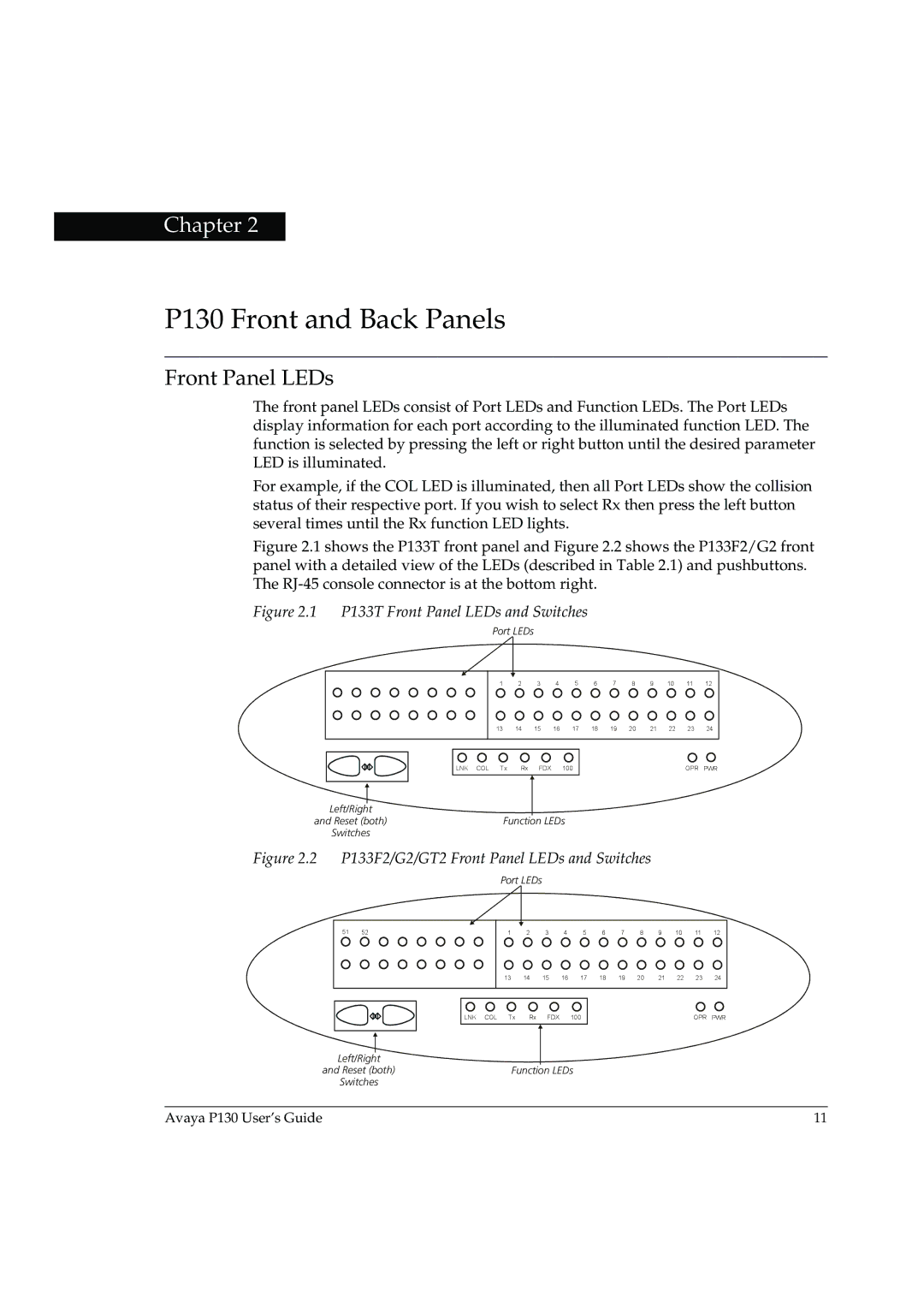
The front panel LEDs consist of Port LEDs and Function LEDs. The Port LEDs display information for each port according to the illuminated function LED. The function is selected by pressing the left or right button until the desired parameter LED is illuminated.
For example, if the COL LED is illuminated, then all Port LEDs show the collision status of their respective port. If you wish to select Rx then press the left button several times until the Rx function LED lights.
Figure 2.1 shows the P133T front panel and Figure 2.2 shows the P133F2/G2 front panel with a detailed view of the LEDs (described in Table 2.1) and pushbuttons. The RJ-45 console connector is at the bottom right.
Figure 2.1 P133T Front Panel LEDs and Switches
Port LEDs
|
|
|
|
|
|
|
|
|
|
|
|
|
|
|
|
|
|
|
| 1 | 2 | 3 | 4 | 5 | 6 | 7 | 8 | 9 | 10 | 11 | 12 |
|
|
|
| 13 | 14 | 15 | 16 | 17 | 18 | 19 | 20 | 21 | 22 | 23 | 24 |
|
|
|
|
|
|
|
|
|
|
|
|
|
|
|
|
|
|
|
| LNK COL Tx | Rx | FDX |
| 100 |
|
|
|
|
| OPR | PWR |
|
|
|
|
|
|
|
|
|
| ||||||
|
|
|
|
|
|
|
|
|
Left/Right
and Reset (both)Function LEDs
Switches
Figure 2.2 P133F2/G2/GT2 Front Panel LEDs and Switches
Port LEDs
|
|
|
|
|
|
|
|
|
|
|
|
|
|
|
|
|
|
51 | 52 |
|
|
| 1 | 2 | 3 | 4 | 5 | 6 | 7 | 8 | 9 | 10 | 11 | 12 | |
|
|
|
|
|
| 13 | 14 | 15 | 16 | 17 | 18 | 19 | 20 | 21 | 22 | 23 | 24 |
|
|
|
|
|
|
|
|
|
|
|
|
|
|
|
|
|
|
|
|
|
|
| LNK COL | Tx | Rx | FDX |
| 100 |
|
|
|
|
| OPR | PWR |
|
|
|
|
|
|
|
|
|
|
| |||||||
|
|
|
|
|
|
|
|
|
| ||||||||
Left/Right
and Reset (both)Function LEDs
Switches
Avaya P130 User’s Guide | 11 |