2 Planning the
Since the
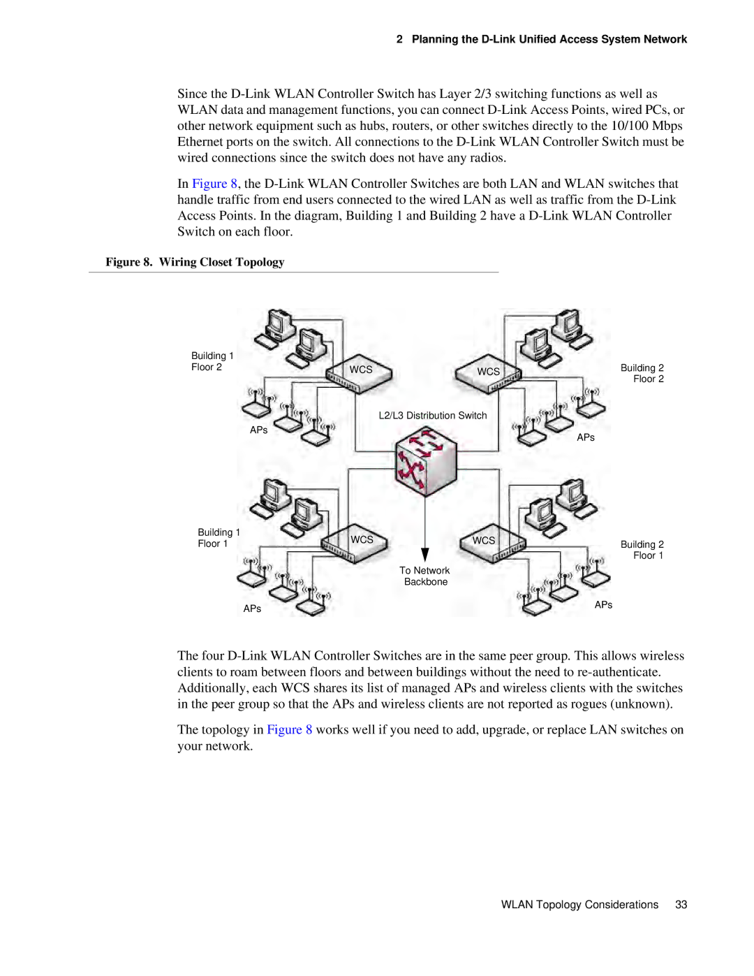
In Figure 8, the
Figure 8. Wiring Closet Topology
Building 1 |
|
|
|
Floor 2 | WCS | WCS | Building 2 |
|
|
| Floor 2 |
|
| L2/L3 Distribution Switch |
|
| APs |
| APs |
|
|
|
Building 1 | WCS |
| WCS |
|
Floor 1 |
| Building 2 | ||
|
|
|
| Floor 1 |
|
| To Network |
| |
|
| Backbone |
| |
| APs |
|
| APs |
|
|
|
| |
The four
The topology in Figure 8 works well if you need to add, upgrade, or replace LAN switches on your network.
WLAN Topology Considerations 33