Now tighten the two screws at adjacent ends of the module into the available screw holes on the Switch. The upgraded Switch is now ready for use.
Figure 24. DWS-3026 with optional DEM-410X module installed
Connecting to the External Redundant Power System
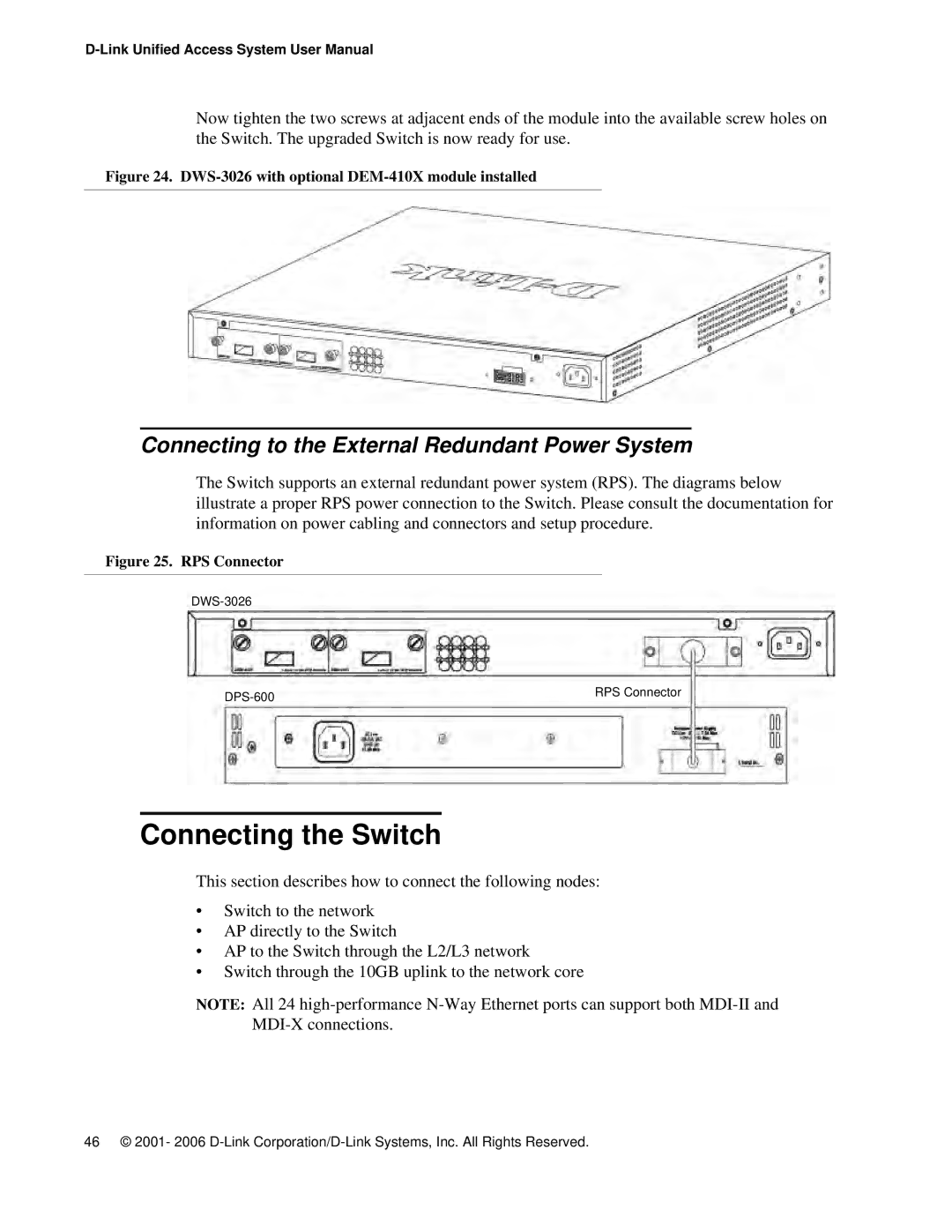
The Switch supports an external redundant power system (RPS). The diagrams below illustrate a proper RPS power connection to the Switch. Please consult the documentation for information on power cabling and connectors and setup procedure.
Figure 25. RPS Connector
RPS Connector | |
|
Connecting the Switch
This section describes how to connect the following nodes:
•Switch to the network
•AP directly to the Switch
•AP to the Switch through the L2/L3 network
•Switch through the 10GB uplink to the network core
NOTE: All 24
46 © 2001- 2006