L3 Roaming Example
the wireless interface on the switch, it is essentially a permanent logical inter- face and cannot have an IP address of 127.0.0.1. You must create a dedicated subnet for the loopback interface, and other devices on the network must be able to contact the IP address of the loopback interface.
You must create static routes so other devices can find the loopback interface.
The advantage of defining a loopback interface is that the interface never goes down. The disadvantage is that network configuration is more complex because the loopback interface is located on its own subnet and the rest of the network must know how to get to the subnet.
The network must have routes between the WCS and the APs to manage. The APs must be able to ping the IP address of the loopback interface used as the WLAN interface on the WCS.
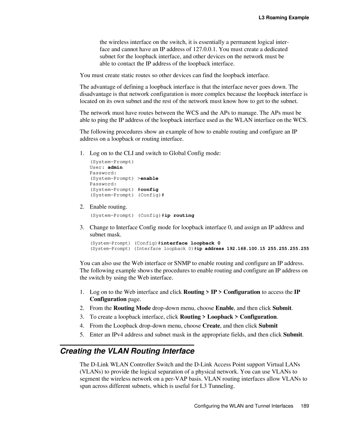
The following procedures show an example of how to enable routing and configure an IP address on a loopback or routing interface.
1. Log on to the CLI and switch to Global Config mode:
2. Enable routing.
3.Change to Interface Config mode for loopback interface 0, and assign an IP address and subnet mask.
You can also use the Web interface or SNMP to enable routing and configure an IP address. The following example shows the procedures to enable routing and configure an IP address on the switch by using the Web interface.
1.Log on to the Web interface and click Routing > IP > Configuration to access the IP Configuration page.
2.From the Routing Mode
3.To create a loopback interface, click Routing > Loopback > Configuration.
4.From the Loopback
5.Enter an IPv4 address and subnet mask in the appropriate fields, and then click Submit.
Creating the VLAN Routing Interface
The
Configuring the WLAN and Tunnel Interfaces 189
