C
L3 Roaming Example
The example in this appendix describes how to configure a
•Configuring the WLAN and Tunnel Interfaces
•Configuring the L3 Tunnel Network
•Configuring DHCP Relay and the DHCP Server
•Setting the MTU Size
Configuring the WLAN and Tunnel Interfaces
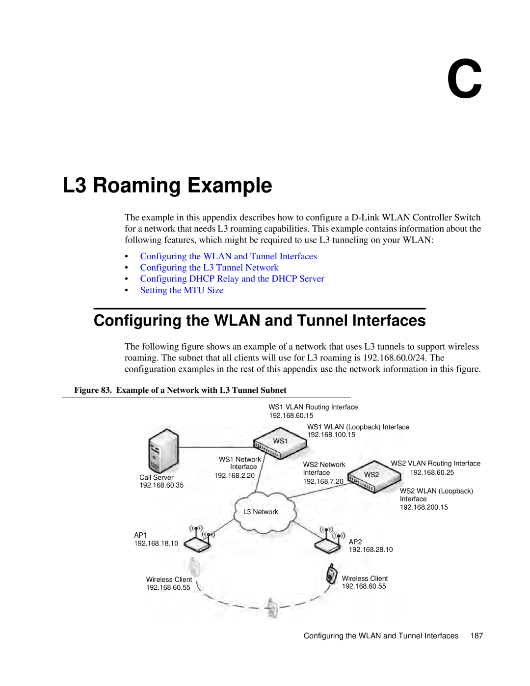
The following figure shows an example of a network that uses L3 tunnels to support wireless roaming. The subnet that all clients will use for L3 roaming is 192.168.60.0/24. The configuration examples in the rest of this appendix use the network information in this figure.
Figure 83. Example of a Network with L3 Tunnel Subnet
WS1 VLAN Routing Interface 192.168.60.15
WS1 WLAN (Loopback) Interface 192.168.100.15
| WS1 |
|
|
|
| WS1 Network | WS2 Network |
| WS2 VLAN Routing Interface |
| Interface |
| ||
Call Server | 192.168.2.20 | Interface | WS2 | 192.168.60.25 |
192.168.7.20 |
| |||
192.168.60.35 |
|
|
| |
|
|
| WS2 WLAN (Loopback) | |
|
|
|
| |
|
|
|
| Interface |
| L3 Network |
|
| 192.168.200.15 |
|
|
|
|
AP1
192.168.18.10 | AP2 |
| 192.168.28.10 |
Wireless Client | Wireless Client |
192.168.60.55 | 192.168.60.55 |
Configuring the WLAN and Tunnel Interfaces 187
