Table 2. LED Description
LED | Description |
10GE Port LEDs | |
| a blinking green light indicates activity on the port. These LEDs remain dark |
| if there is no link/activity on the port. |
|
|
Combo SFP Ports | The LED indicators for the Combo ports are located above the ports and |
| numbered 1 – 4 for Combo 1, Combo 2, Combo 3, and Combo 4 ports. A |
| steady green light indicates a valid link on the port while a blinking green |
| light indicates activity on the port. These LEDs remain dark if there is no |
| link/activity on the port. |
|
|
Rear Panel Description
The AC power connector is a standard
The rear panel also includes an outlet for an optional external power supply. When a power failure occurs, the optional external RPS will immediately and automatically assume the power supply for the Switch.
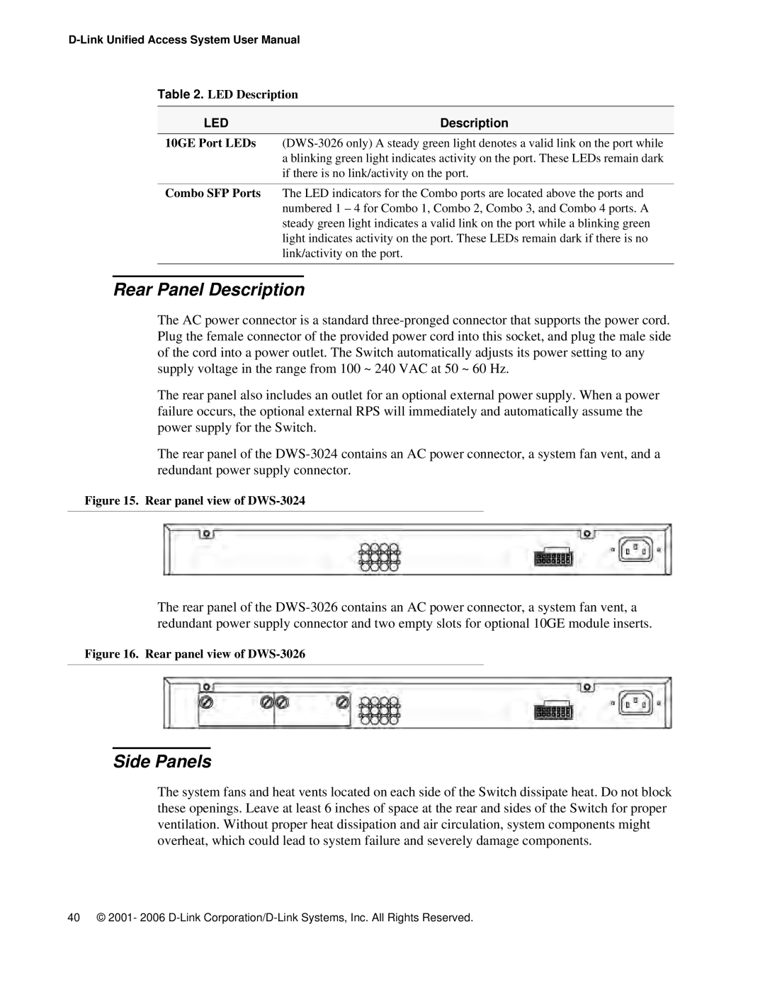
The rear panel of the
Figure 15. Rear panel view of DWS-3024
The rear panel of the
Figure 16. Rear panel view of DWS-3026
Side Panels
The system fans and heat vents located on each side of the Switch dissipate heat. Do not block these openings. Leave at least 6 inches of space at the rear and sides of the Switch for proper ventilation. Without proper heat dissipation and air circulation, system components might overheat, which could lead to system failure and severely damage components.
40 © 2001- 2006