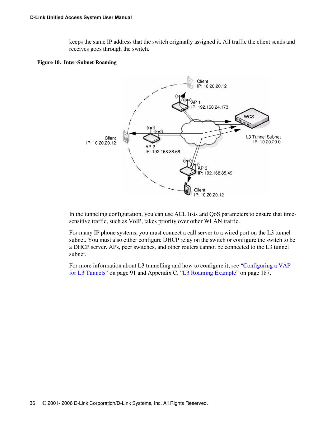
keeps the same IP address that the switch originally assigned it. All traffic the client sends and receives goes through the switch.
Figure 10. Inter-Subnet Roaming
|
| Client | ||
|
| IP: 10.20.20.12 | ||
| AP 1 | |||
| IP: 192.168.24.173 | |||
|
|
|
| WCS |
Client |
|
|
| L3 Tunnel Subnet |
|
|
| ||
|
|
| ||
IP: 10.20.20.12 |
|
|
| IP: 10.20.20.0 |
| AP 2 | |||
| IP: 192.168.38.66 | |||
|
| AP 3 | ||
|
| IP: 192.168.85.49 | ||
| Client | |||
| IP: 10.20.20.12 | |||
In the tunneling configuration, you can use ACL lists and QoS parameters to ensure that time- sensitive traffic, such as VoIP, takes priority over other WLAN traffic.
For many IP phone systems, you must connect a call server to a wired port on the L3 tunnel subnet. You must also either configure DHCP relay on the switch or configure the switch to be a DHCP server. APs, peer switches, and other routers cannot be connected to the L3 tunnel subnet.
For more information about L3 tunnelling and how to configure it, see “Configuring a VAP for L3 Tunnels” on page 91 and Appendix C, “L3 Roaming Example” on page 187.
36 © 2001- 2006