5.MIDI IN jack [MIDI IN] (Connector: DIN 5-pin)
Connect this jack to the MIDI OUT jack of an external MIDI device. You can control the VR800 remotely by inputting MMC (MIDI Machine Control) command or FEX (Fostex System Exclusive Message) here.
MIDI
IN
Refer to page 68 for more information on using the MIDI IN
jack.
6. Word Out jack [WORD OUT] (Connector: BNC)
Word clock signal from the VR800 is output here.
This jack and WORD IN of the external digital equipment must be connected if the WORD IN connector ia provided in the external digital equipment (digital mixer, etc.) which is connected to the VR800.
Refer to the separate “Quick Operation Guide” for operating
procedures.
VR800 Owner’s Manual (Names and Functions)
7. AC IN connector
The power cable packaged with this recorder ia connected here.
Note: Always plug the power cable to the recorder before
plugging the cable into the wall outlet.
8. Power switch [POWER]
This switch turns power on and off to the VR800.
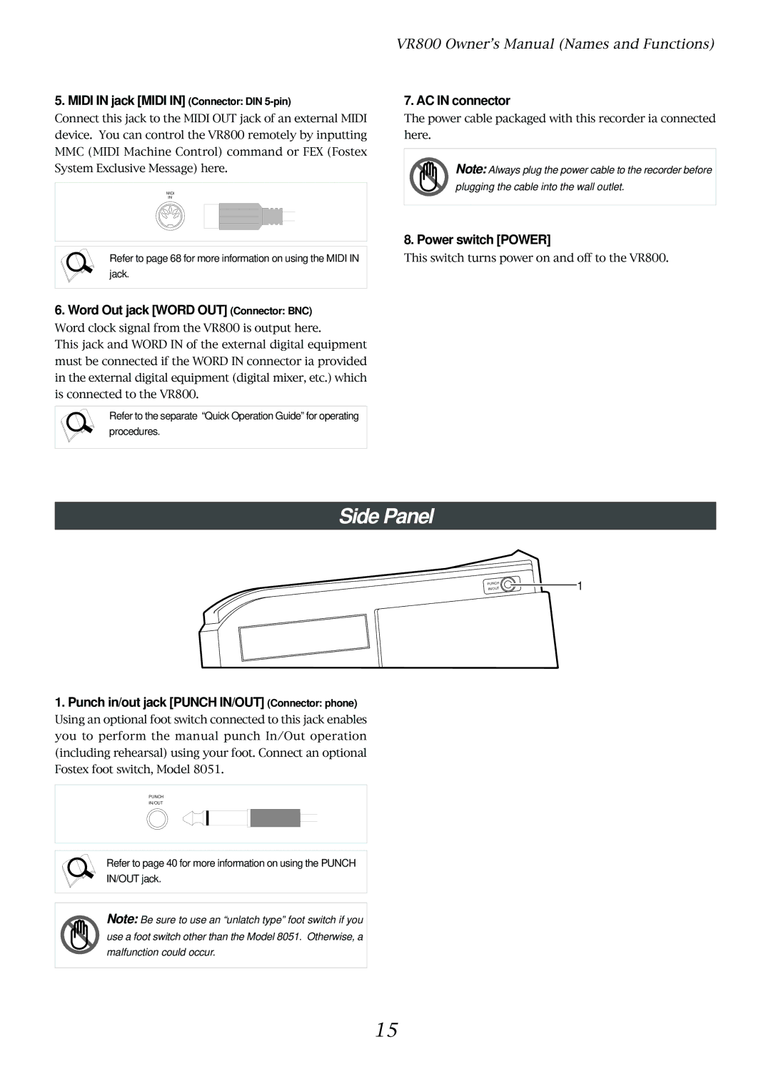
Side Panel
PUNCH
IN/OUT
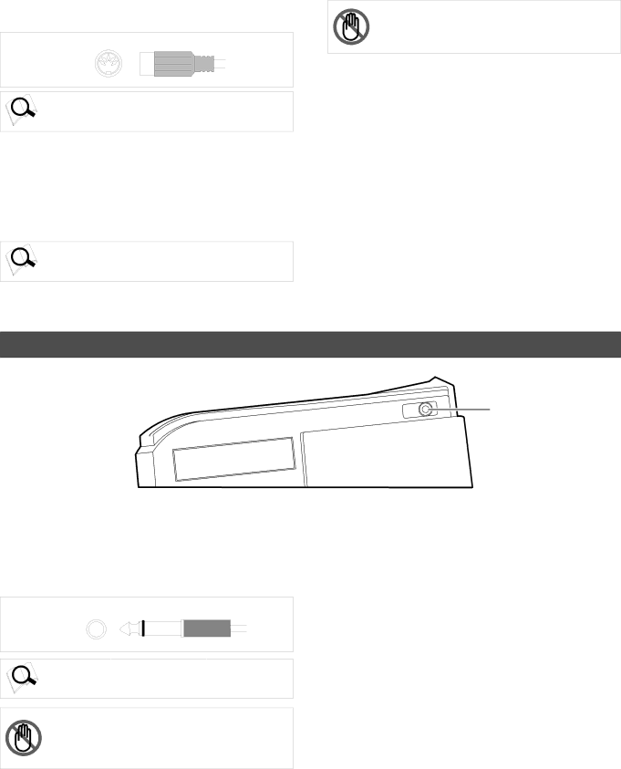
1. Punch in/out jack [PUNCH IN/OUT] (Connector: phone)
Using an optional foot switch connected to this jack enables you to perform the manual punch In/Out operation (including rehearsal) using your foot. Connect an optional Fostex foot switch, Model 8051.
PUNCH
IN/OUT
Refer to page 40 for more information on using the PUNCH
IN/OUT jack.
Note: Be sure to use an “unlatch type” foot switch if you use a foot switch other than the Model 8051. Otherwise, a malfunction could occur.
1
15