Installing Multiple Carriers | Installing the MDW 9031/9031DCP Pocket Phone 2 | ||
|
|
|
|
3If you are using a Model 117A4 carrier, verify that the carrier’s CONTROL/EXPANSION LED is lit and that its color is green. This is correct for a
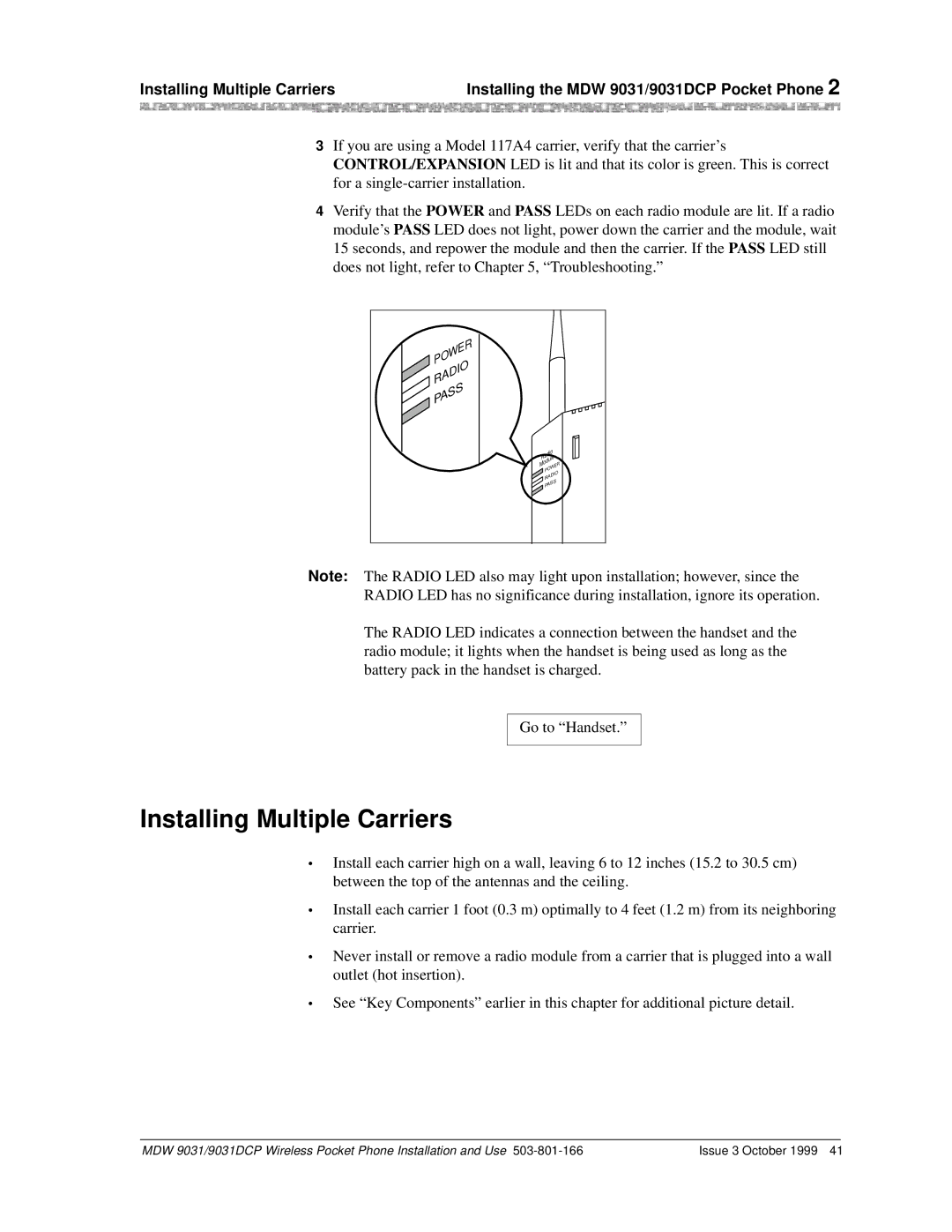
4Verify that the POWER and PASS LEDs on each radio module are lit. If a radio module’s PASS LED does not light, power down the carrier and the module, wait 15 seconds, and repower the module and then the carrier. If the PASS LED still does not light, refer to Chapter 5, “Troubleshooting.”
POWER
RADIO
![]() PASS
PASS
Radio | ||
ModuleER | ||
W | ||
PO | DIO | |
RA | ||
| ||
PASS | ||
Note: The RADIO LED also may light upon installation; however, since the
RADIO LED has no significance during installation, ignore its operation.
The RADIO LED indicates a connection between the handset and the radio module; it lights when the handset is being used as long as the battery pack in the handset is charged.
Go to “Handset.”
Installing Multiple Carriers
•Install each carrier high on a wall, leaving 6 to 12 inches (15.2 to 30.5 cm) between the top of the antennas and the ceiling.
•Install each carrier 1 foot (0.3 m) optimally to 4 feet (1.2 m) from its neighboring carrier.
•Never install or remove a radio module from a carrier that is plugged into a wall outlet (hot insertion).
•See “Key Components” earlier in this chapter for additional picture detail.
MDW 9031/9031DCP Wireless Pocket Phone Installation and Use | Issue 3 October 1999 41 |