2 Installing the MDW 9031/9031DCP Pocket Phone | Installing Multiple Carriers | ||
|
|
|
|
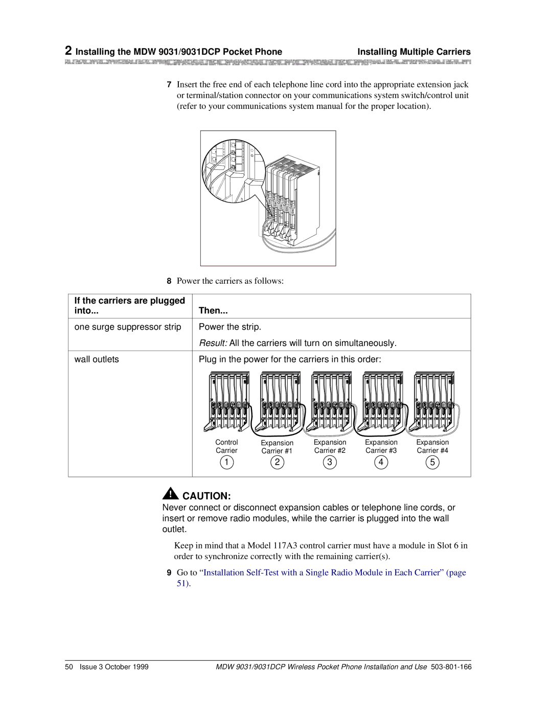
7Insert the free end of each telephone line cord into the appropriate extension jack or terminal/station connector on your communications system switch/control unit (refer to your communications system manual for the proper location).
N | X |
|
S | T |
|
I | E |
|
O | N |
|
N | S |
|
S | I | MUSIC |
| O | |
|
| ON |
| N | HOLD |
| S |
|
8Power the carriers as follows:
If the carriers are plugged | Then... | ||||||||||
into... | |||||||||||
|
|
|
|
|
|
|
|
|
|
|
|
one surge suppressor strip | Power the strip. | ||||||||||
| Result: All the carriers will turn on simultaneously. | ||||||||||
|
|
|
|
|
|
|
|
|
|
|
|
wall outlets | Plug in the power for the carriers in this order: | ||||||||||
|
|
|
|
|
|
|
|
|
|
|
|
|
|
|
|
|
|
|
|
|
|
|
|
1 | 2 | 3 | 4 | 5 | 6 | 1 | 2 | 3 | 4 | 5 | 6 | 1 | 2 | 3 | 4 | 5 | 6 | 1 | 2 | 3 | 4 | 5 | 6 | 1 | 2 | 3 | 4 | 5 | 6 |
Control | Expansion | Expansion | Expansion | Expansion |
Carrier | Carrier #1 | Carrier #2 | Carrier #3 | Carrier #4 |
1 | 2 | 3 | 4 | 5 |
!CAUTION:
Never connect or disconnect expansion cables or telephone line cords, or insert or remove radio modules, while the carrier is plugged into the wall outlet.
Keep in mind that a Model 117A3 control carrier must have a module in Slot 6 in order to synchronize correctly with the remaining carrier(s).
9Go to “ Installation
50 Issue 3 October 1999 | MDW 9031/9031DCP Wireless Pocket Phone Installation and Use |