Installing Multiple Carriers | Installing the MDW 9031/9031DCP Pocket Phone 2 | ||
|
|
|
|
4Place the carrier assembly over the screws, then slide it downward to lock it into place. Be sure that the leftmost carrier is the control carrier. Tighten the screws. Repeat for each carrier.
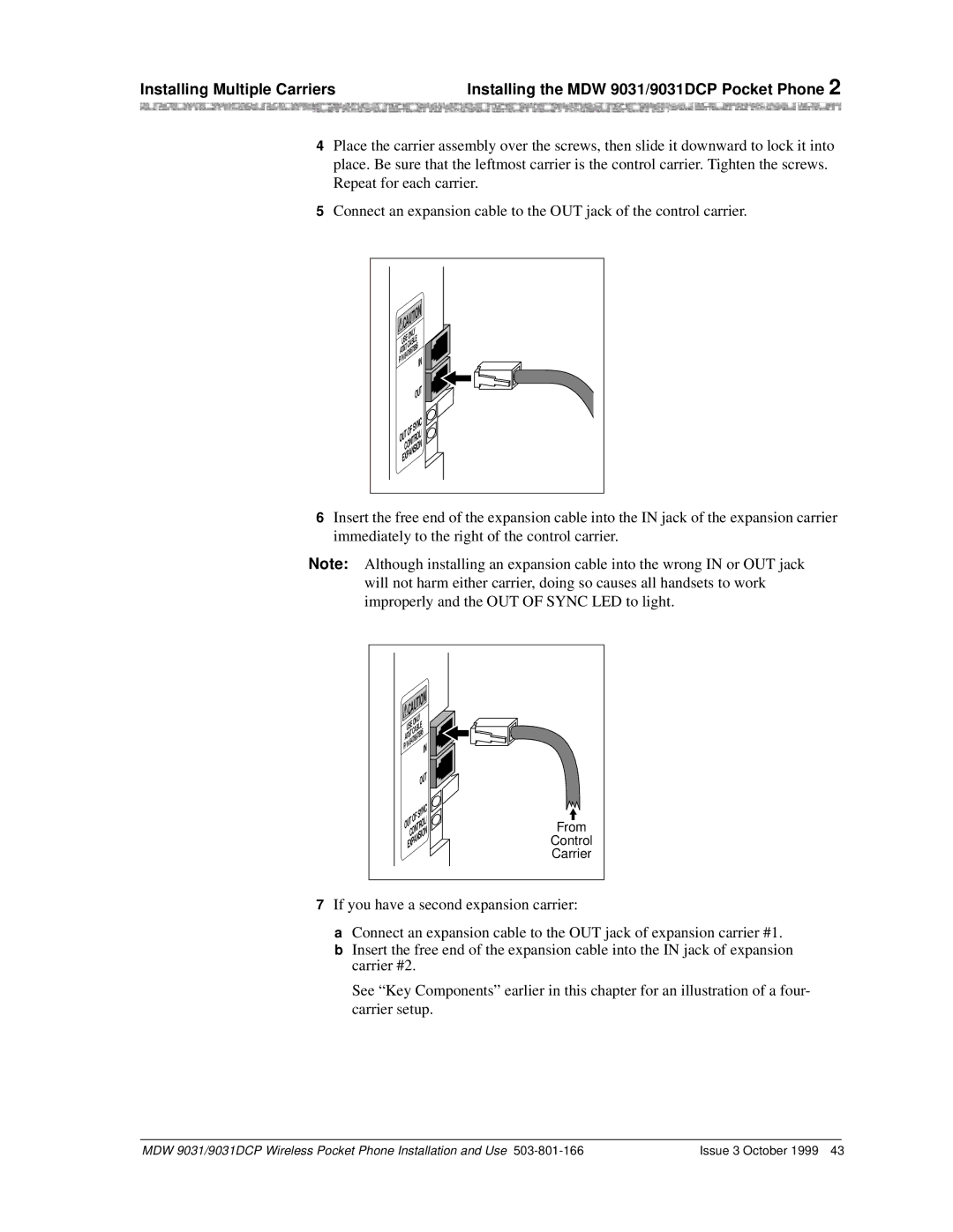
5Connect an expansion cable to the OUT jack of the control carrier.
CAUTION
|
|
|
| LY | |
U | S | EO | N | LE | |
B | |||||
|
|
| C | A | 6 |
AT&T |
| 67 | 89 | ||
|
|
| 76 |
| |
P⁄N | 84 |
|
| ||
|
|
|
|
| |
IN
| OUT |
| YNC |
OF | S |
OUT |
|
CONTROL/ | |
EXPANSION | |
6Insert the free end of the expansion cable into the IN jack of the expansion carrier immediately to the right of the control carrier.
Note: Although installing an expansion cable into the wrong IN or OUT jack will not harm either carrier, doing so causes all handsets to work improperly and the OUT OF SYNC LED to light.
| CAUTION | |||
|
|
| Y |
|
|
| ONL |
| |
| USE |
|
| |
|
| CABLE |
| |
AT&T |
|
| ||
P⁄ | N | 847667896 | ||
|
| IN | ||
|
|
| ||
|
|
|
| |
|
|
|
| T |
|
|
| O | U |
|
|
|
| |
|
| OF | SYNC | |
|
|
|
| |
OUT |
|
| ||
|
| CONTROL/ | ||
| EXPANSION | |||
From
Control
Carrier
7If you have a second expansion carrier:
a Connect an expansion cable to the OUT jack of expansion carrier #1. b Insert the free end of the expansion cable into the IN jack of expansion
carrier #2.
See “Key Components” earlier in this chapter for an illustration of a four- carrier setup.
MDW 9031/9031DCP Wireless Pocket Phone Installation and Use | Issue 3 October 1999 43 |