Operating Instructions Issue 07/04
User Documentation
Micromaster 420 Documentation
Getting Started Guide
Operating Instructions
Parameter List
Operating Instructions
Valid for Release
Micromaster
Online Service & Support
User Documentation
Information is also available from Regional Contacts
Central Technical Support
Use for intended purpose only
Qualified personnel
Safety Instructions
General
Transport & Storage
Commissioning
Dismantling & Disposal
Operation
Repair
Safety Instructions Issue 07/04
Table of Contents
151
152
153
154
List of Illustrations
OFF1
List of Tables
Table of Contents Issue 07/04
Overview
This Chapter contains
Micromaster
Performance Characteristics
Features
Main Characteristics
Protection characteristics
Options
Installation
Installation Issue 07/04
Installation after a Period of Storage
Temperature
General
Ambient operating conditions
Installation and cooling
Humidity
Altitude
Shock and Vibration
Mechanical installation
Removing the Inverter from the rail
Mounting on standard rail, Frame Size a
Fitting the Inverter to a 35 mm standard rail EN
Electrical installation
Inverter must always be grounded
General
Operation with ungrounded IT supplies
Operation with Residual Current Device
Operation with long cables
Power and motor connections
Access to the power and motor terminals
Single Phase
Three Phase
Control terminals
Terminal Designation Function
Avoiding Electro-Magnetic Interference EMI
Action to Take
Screening without a Gland Plate
Screening Methods
Gland Plate
Installation Issue 07/04
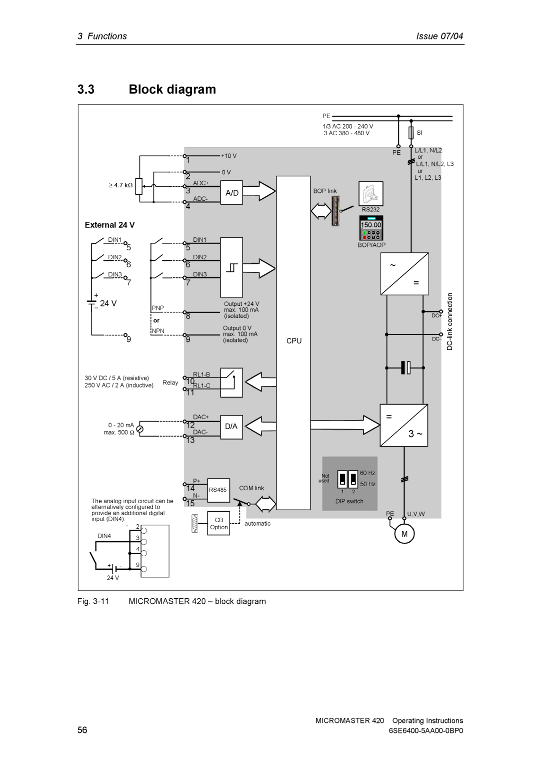
Functions
This Section includes the following
Functions Issue 07/04
Issue 07/04 Functions
Setting / monitoring parameters and parameter attributes
Setting parameters
Parameters
Notation
Monitoring parameters
Attribute Description Group
Inverter
P03053
Rated motor current
P0003 =
P0003 =
P0004 =
Interconnecting signals Bico technology
Significance / command source
Significance
Main setpoint source Supplementary setpoint source
Selection of command/frequency setpoint P0719
Command source
BI Binector Input, signal receiver P parameters
BO Binector Output, signal source r parameters
Abbreviation and symbol Name Function
Bico technology
CI Connector Input, signal sink P parameters
CO Connector Output, signal source r parameters
P1070 =
P0840 =
P2051 =
P0731 =
Parameter Designation Value 100 % Units
Reference quantities
Interface 100 %
Example
Operator panels for Micromaster
Description of the BOP Basic Operator Panel
Description of the AOP Advanced Operator Panel
Keys and their functions on the operator panel BOP / AOP
Operator Function Effects Panel/key
Step Result on the display
Changing parameters using the operator panel
Changing P0004 parameter filter function
Block diagram
External 24
Factory setting
Parameter Function
13 Recommended wiring for the factory setting
14 Procedure when commissioning
Commissioning
Check list
1 50/60 Hz setting
15 DIP switch to change-over between 50/60 Hz
Factory setting User access level
Quick commissioning
Parameterizing the drive with BOP or AOP
Commissioning parameter
Europe kW, frequency default 50 Hz
Rated motor power
Europe/ North America
Rated motor voltage
Selection of command source
Control mode
End of quick commissioning/ drive setting
Selection of frequency setpoint
17 Example of a typical motor rating plate
IEC Motor
Nema Motor
Hz characteristic
19 Star / delta circuit configurations
87 Hz
Calculating the motor / control data
Motor data identification stator resistance
Ambient motor temperature entered in C
Power-up the motor
Disabled
Motor data identification routine
Serial Interface USS
Commissioning the application
Adapting the drive inverter to the application
5.2 Selection of command source
Digital input DIN
Selection of frequency setpoint
Digital output Dout
5.5
Analog input ADC
5.7 Analog output DAC
Motor potentiometer MOP
Fixed frequency FF
5.10 JOG
Ramp-function generator HLG
Reference/limit frequencies
Motor control
Acceleration boost entered in %
Starting boost entered in %
Programmable V/f freq .0 Hz coord
Slip compensation entered in %
Inverter/motor protection
Holding brake
Inverter-specific Functions Flying start
Automatic restart
DC braking
Compound braking
Vdc controller
PID controller
Max. value for PID feedback
Sets lower limit for the PID controller output in %
Example
Parameter Parameter text Example
Series commissioning
MM4
Issue 07/04 Functions
Factory reset
Parameter reset to the factory setting
Reset to the factory setting
Inputs / outputs
Digital inputs DIN
Parameter value Significance
P0701 P0703 digital inputs 1-3 or P0707 P0703 analog input
Example
Bico parameterization
Digital output Dout
11 Parameter P0731 frequently used functions / states
Analog input ADC
ADC channel
Wire breakage monitoring
26 Wire breakage monitoring
27 Signal output through the DAC channel
Analog output DAC
Communications
Starter USS
BOP link interface BOP on BOP link USS on BOP link
COM link interface CB on COM link USS on COM link
USS at the COM link RS485
USS bus configuration via COM link RS485
30 RS485 Terminator
Fixed frequencies FF
Direct selection
Direct selection + on command
Binary-coded selection + on command
R0722.1
Motorized potentiometer MOP
Selecting via serial interfaces
AOP at the BOP link
Selecting via BOP or AOP
Parameters / keys
10 JOG
35 JOG counter-clockwise and JOG clockwise
105
PID controller technological controller
36 Structure of the technological controller PID controller
Parameterizations
PID motorized potentiometer PID-MOP
PID motorized potentiometer Motorized potentiometer
PID fixed setpoint PID-FF
Setpoint channel
Summation and modification of the frequency setpoint AFM
111
Ramp-function generator RFG
With rounding
P1132 P1133
P1134 =
19 Bico parameters for ramp-function generator
Parameter Description
12.3 OFF/braking functions
OFF1
OFF2
Parameter setting Command source
Manual / automatic operation
Value Command source Setpoint source
Motor holding brake MHB
On / OFF1/OFF3
On / OFF2
49 Motor holding brake after OFF2
121
Electronic brakes
14.1 DC braking
Sequence ➀
51 DC braking after OFF1 / OFF3
Sequence ➁
52 DC braking after external selection
Compound braking
53 Compound braking
126
Automatic restart
Line undervoltage brownout
Line failure blackout
Blackout Brownout
128
Flying restart
Flying restart active Search direction
130
Closed-loop Vdc control
Vdcmax controller
DC link undervoltage
Cause
132
Monitoring functions / messages
General monitoring functions / messages
Function chart
Functions / states
Thermal motor model
Features
Thermal motor protection and overload responses
136
19.2 PTC temperature sensor
Temperature Classes
58 Connecting a temperature sensor to Micromaster
General overload monitoring
Power module protection
Fault and shutdown
I2t monitoring
Heatsink temperature
Thermal monitoring functions and overload responses
Reducing the output frequency P0290 = 0,2
Reducing the pulse frequency P0290 = 2
Disadvantage
No reduction P0290 =
Open-loop/closed-loop control technique
21.1 Control
27 V/f characteristic parameter P1300
Use / property
Voltage boost
Parameter Voltage boost Explanation
146
21.1.2 V/f open-loop control with flux current control FCC
Slip compensation
62 Slip compensation
21.1.4 V/f resonance damping
63 Effect of V/f resonance damping
Current limiting Imax controller
Imax controller setpoint
Troubleshooting
Troubleshooting with the SDP
Troubleshooting Issue 07/04
Troubleshooting with the BOP
Alarm messages
Fault messages and alarm messages
Fault messages
Suppressing fault / alarm messages
156
Micromaster 420 specifications
Micromaster 420 specifications Issue 07/04
Feature Specification
KHz 10 kHz 12 kHz 14 kHz 16 kHz
Lbs
2AB11 2AB12 2AB13 2AB15 2AB17 2AB21 2AB22 2AB23
1BA1 5BA1
Input voltage range AC 200 V 240 V, ± 10 % Unfiltered
2UC11 2UC12 2UC13 2UC15 2UC17 2UC21 2UC22 2UC23
KVA
Awg
2UC25
2UC12 2UC13
1BA1 5BA1 2BA1
2BA1 0BA1
2AD23 2AD24
2AD31
2UD25 2UD27 2UD31
Input voltage range AC 380 V 480 V, ± 10 % Unfiltered
2UD13 2UD15 2UD17 2UD21 2UD22 2UD23 2UD24
Device-dependent options
Options
Device-independent options
Options Issue 07/04
Electro-magnetic compatibility EMC
Electro-magnetic compatibility EMC
Self-certification
Technical construction file
EC type examination certificate
EMC Directive Compliance with Imminent Harmonics Regulations
Classification of EMC performance
Class 1 General Industrial
Class 2 Filtered Industrial
EMC Phenomenon Standard Level
171
Class
Model Remarks
Class 1 General Industrial
Appendices Changing the OperatorPanel
Removing Covers
Removing Covers Frame Size a
6SE6400-5AA00-0BP0
Removing ‘Y’ Cap
Removing ‘Y’ Cap Frame Size a
Issue 07/04 Removing ‘Y’ Cap
Removing fan
Removing fan, Frame Size a
Removing fan, Frame Sizes B and C
Applicable Standards
List of Abbreviations
COM
List of Abbreviations Issue 07/04
PPO
Index
Issue 07/04 Index
Ungrounded IT supplies
Suggestions and/or Corrections
Suggestions Corrections
188
View of Unit Frame Size a
Frame Size B & C
Siemens Aktiengesellschaft