4.8 Bottom cover assembly | 4 Replacement Procedures |
4.8Bottom cover assembly
Removing the bottom cover assembly
The following describes the procedure for removing the bottom cover assembly (See Figure
1.Remove the following screw securing LCD harness cover and remove the LCD harness cover.
M2.5x4.0B | FLAT BIND screw | x1 |
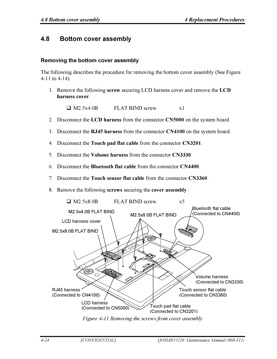
2.Disconnect the LCD harness from the connector CN5000 on the system board.
3.Disconnect the RJ45 harness from the connector CN4100 on the system board.
4.Disconnect the Touch pad flat cable from the connector CN3201.
5.Disconnect the Volume harness from the connector CN3330.
6.Disconnect the Bluetooth flat cable from the connector CN4400.
7.Disconnect the Touch sensor flat cable from the connector CN3360.
8.Remove the following screws securing the cover assembly.
M2.5x8.0B | FLAT BIND screw | x5 | ||
M2.5x4.0B FLAT BIND |
| Bluetooth flat cable | ||
M2.5x8.0B FLAT BIND | (Connected to CN4400) | |||
|
| |||
LCD harness cover
M2.5x8.0B FLAT BIND
| Volume harness |
| (Connected to CN3330) |
RJ45 harness | Touch sensor flat cable |
(Connected to CN4100) | (Connected to CN3360) |
LCD harness
(Connected to CN5000) Touch pad flat cable (Connected to CN3201)
Figure 4-11 Removing the screws from cover assembly
[CONFIDENTIAL] | QOSMIO G20 Maintenance Manual |