4.13 Optical disk drive | 4 Replacement Procedures |
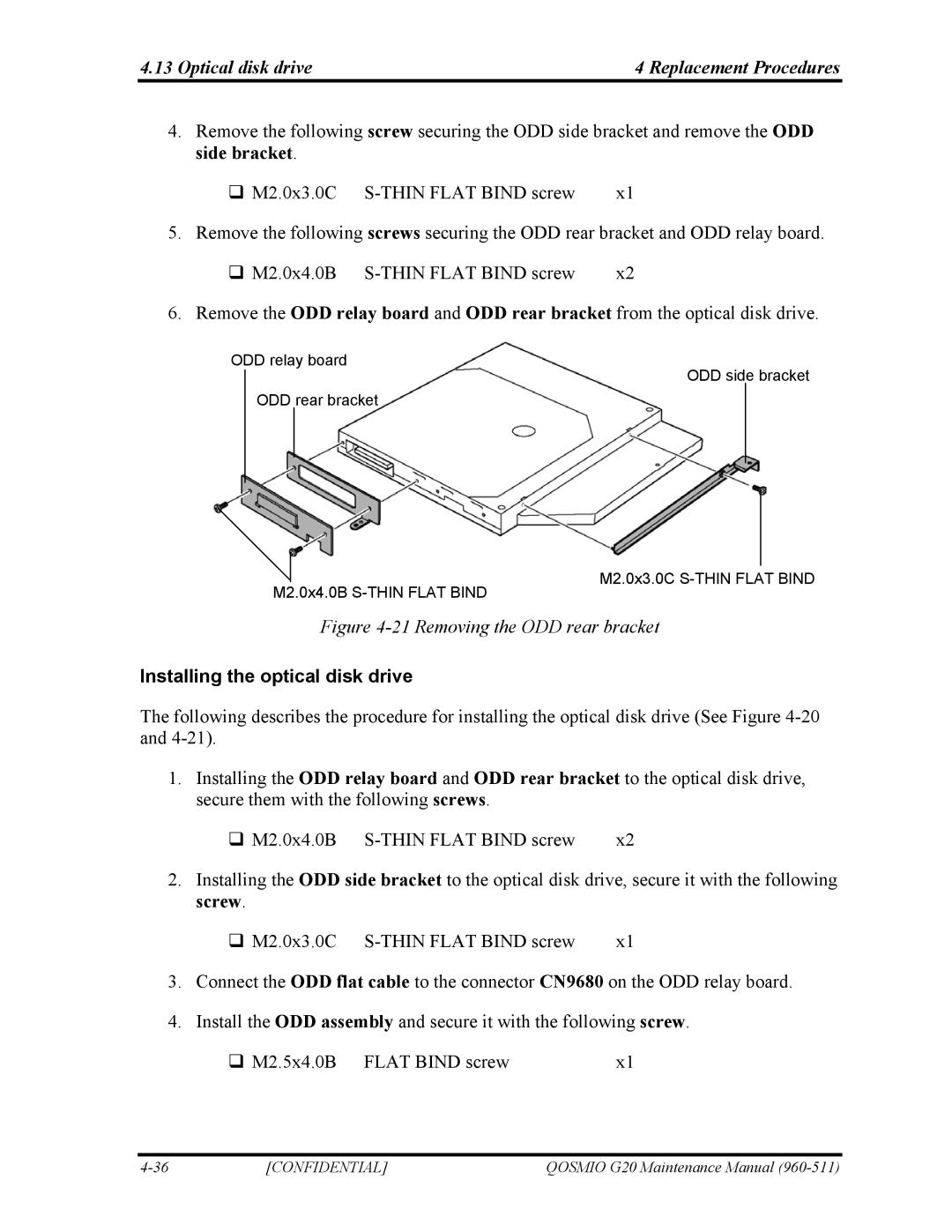
4.Remove the following screw securing the ODD side bracket and remove the ODD side bracket.
| M2.0x3.0C | x1 | |||||||||
5. | Remove the following screws securing the ODD rear bracket and ODD relay board. | ||||||||||
| M2.0x4.0B | x2 | |||||||||
6. | Remove the ODD relay board and ODD rear bracket from the optical disk drive. | ||||||||||
|
|
|
|
|
|
|
|
|
| ||
|
| ODD relay board |
|
|
|
|
|
| |||
|
|
|
|
|
|
|
|
| ODD side bracket |
| |
|
|
|
|
|
|
|
| ||||
|
|
|
|
|
|
|
|
|
|
|
|
|
|
|
| ODD rear bracket |
|
|
|
| |||
|
|
|
|
|
|
|
|
|
|
|
|
|
|
|
|
|
|
|
|
|
|
|
|
|
|
|
|
|
|
|
|
|
|
|
|
M2.0x4.0B
M2.0x3.0C
Figure 4-21 Removing the ODD rear bracket
Installing the optical disk drive
The following describes the procedure for installing the optical disk drive (See Figure
1.Installing the ODD relay board and ODD rear bracket to the optical disk drive, secure them with the following screws.
M2.0x4.0B | x2 |
2.Installing the ODD side bracket to the optical disk drive, secure it with the following screw.
M2.0x3.0C | x1 |
3.Connect the ODD flat cable to the connector CN9680 on the ODD relay board.
4.Install the ODD assembly and secure it with the following screw.
M2.5x4.0B FLAT BIND screw | x1 |
[CONFIDENTIAL] | QOSMIO G20 Maintenance Manual |