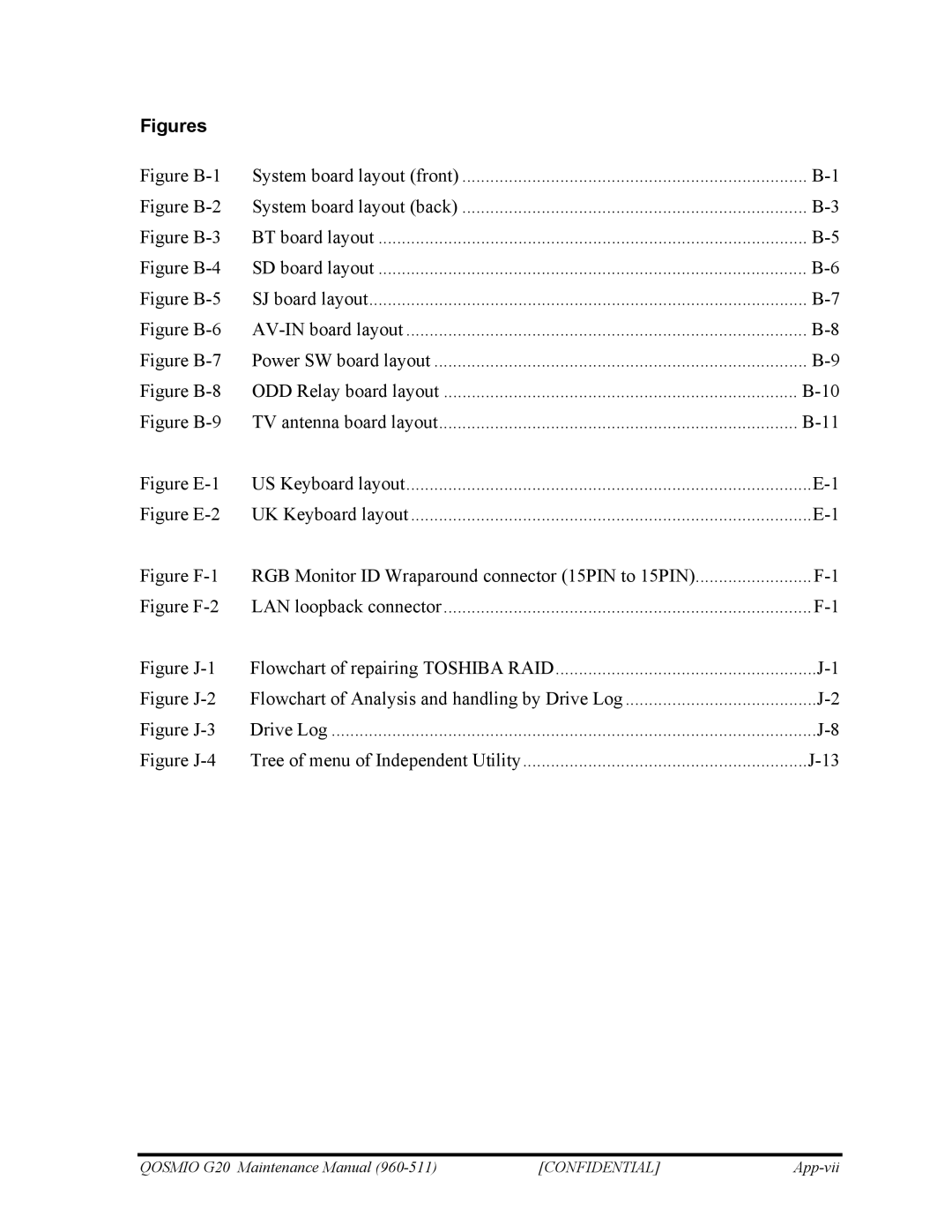
Figures |
|
|
Figure | System board layout (front) | |
Figure | System board layout (back) | |
Figure | BT board layout | |
Figure | SD board layout | |
Figure | SJ board layout | |
Figure | ||
Figure | Power SW board layout | |
Figure | ODD Relay board layout | |
Figure | TV antenna board layout | |
Figure | US Keyboard layout | |
Figure | UK Keyboard layout | |
Figure | RGB Monitor ID Wraparound connector (15PIN to 15PIN) | |
Figure | LAN loopback connector | |
Figure | Flowchart of repairing TOSHIBA RAID | |
Figure | Flowchart of Analysis and handling by Drive Log | |
Figure | Drive Log | |
Figure | Tree of menu of Independent Utility |
QOSMIO G20 Maintenance Manual | [CONFIDENTIAL] |
