SERVSWITCH™ MULTI

Appendix A: Configuration Charts

The information sheet on the next page and the charts on the six pages that follow are designed to help you keep track of the configuration of your ServSwitch Multi system. First make one copy of page 139. Then, for each ServSwitch Multi Base Unit, MX, EXP, or SB in your system, make a copy of all of the applicable pages from 140 to 143. Also make a copy of pages 144 and 145 for each ServSwitch Multi Hub in your system. As you configure and install Cards, Modules, and associated equipment in your system, please make a complete record of each channel’s configuration information on the appropriate pages, and update this information whenever you make changes. If you need to contact Black Box Technical Support, have all this info on hand (and please fill out a copy of the Problem Report in Appendix B) before you call.

The six pages from page 140 through page 145 are divided into six configuration charts, one chart for each type of configurable ServSwitch Multi add-in Card or Module. For the Cards, fill out one record in a copy of the appropriate chart for each channel that you’ve installed a given type of Card in: Chart A-1 for CPU-Interface Card channels, A-2 for User-Interface Card channels, A-3 for Expansion Transmit Card channels, or A-4 for Expansion Receive Card channels. For the Modules, fill out one whole chart for each Module: Chart A-5 for Transmit Modules or A-6 for Receive Modules.

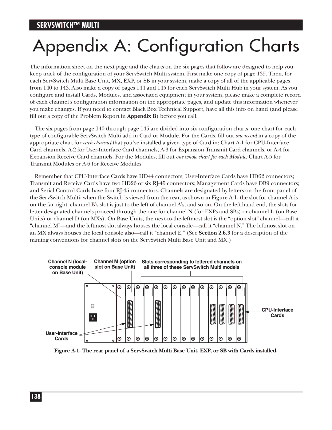
Remember that CPU-Interface Cards have HD44 connectors; User-Interface Cards have HD62 connectors; Transmit and Receive Cards have two HD26 or six RJ-45 connectors; Management Cards have DB9 connectors; and Serial Control Cards have four RJ-45 connectors. Channels are designated by letters on the front panel of the ServSwitch Multi; when the Switch is viewed from the rear, as shown in Figure A-1, the slot for channel A is on the far right, channel B’s slot is just to the left of channel A’s, and so on. On the left-hand end, the slots for letter-designated channels proceed through the one for channel N (for EXPs and SBs) or channel L (on Base Units) or channel D (on MXs). On Base Units, the next-to-the-leftmost slot is the “option slot” channel—call it “channel M”—and the leftmost slot always houses the local console—call it “channel N.” The leftmost slot on an MX always houses the local console also—call it “channel E.” (See Section 2.6.3 for a description of the naming conventions for channel slots on the ServSwitch Multi Base Unit and MX.)

Channel N (local-

Channel M (option

Slots corresponding to lettered channels on

console module

slot on Base Unit)


all three of these ServSwitch Multi models

on Base Unit)


User-Interface

Cards

CPU-Interface

Cards

Figure A-1. The rear panel of a ServSwitch Multi Base Unit, EXP, or SB with Cards installed.

138
Page 139
Image 139
Black Box KV162A manual Appendix a Configuration Charts