APPENDIX A: Configuration Charts
Chart
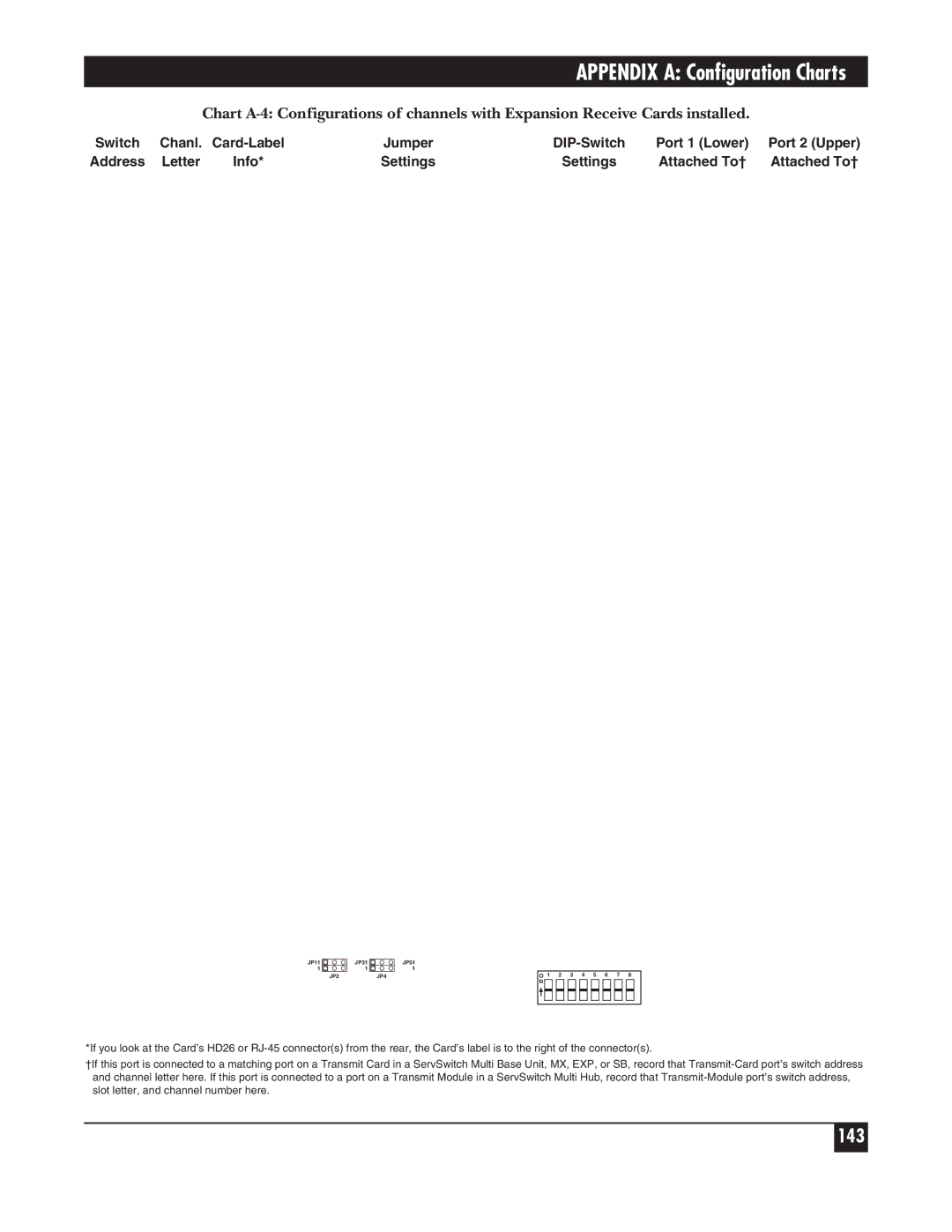
Switch | Chanl. | Jumper | Port 1 (Lower) | Port 2 (Upper) | ||
Address | Letter | Info* | Settings | Settings | Attached To† | Attached To† |
JP11 | JP31 | JP51 |
1 | 1 | 1 |
JP2 |
| JP4 |
O | 1 | 2 | 3 | 4 | 5 | 6 | 7 |
| 8 |
| ||||||
N |
|
|
|
|
|
|
|
|
|
|
|
|
|
|
|
|
|
|
|
|
|
|
|
|
|
|
|
|
|
|
|
|
|
|
|
|
|
|
|
|
|
|
|
|
|
|
|
|
|
|
|
|
|
|
|
|
|
|
|
|
|
|
|
|
|
|
|
*If you look at the Card’s HD26 or
†If this port is connected to a matching port on a Transmit Card in a ServSwitch Multi Base Unit, MX, EXP, or SB, record that