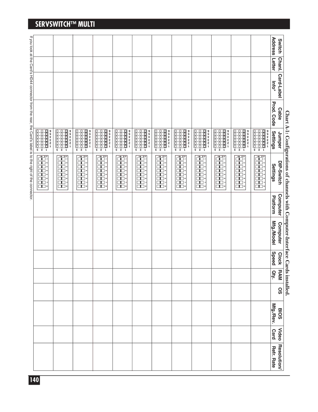
System
Doc. No. 590-054-001 Rev. B
KV150A-R2 KV155A KV160A-R2 KV162A KV170RA
Customer Support Information
Welcome to the ServSwitch Family
THE SERVSWITCH FAMILY
continued on next page
KV150A-R2 KV155A KV160A-R2 KV162RA KV170RA
SERVSWITCH MULTI
KV1601C
KV1602C
FCC, IC, AND NOM STATEMENTS
FEDERAL COMMUNICATIONS COMMISSION AND INDUSTRY CANADA
RADIO-FREQUENCY INTERFERENCE STATEMENTS
18. Servicio por personal calificado deberá ser provisto cuando
SERVSWITCH MULTI
Chapter
Contents
SERVSWITCH MULTI
Contents cont’d
Chapter
Page
9.2.3.C Switch Alt. User Module
Overriding the Settings of a CPU-Interface Card’s DIP Switches
Administrator Setup
Chapter
SERVSWITCH MULTI
Contents cont’d
10.3.3.A What Is “Opening a Session”?
10.3.3.B How to Open a Session
Common Problems
TABLE OF CONTENTS
Appendix A Configuration Charts
Appendix B Problem Report
SERVSWITCH MULTI
1. Specifications
Resolution
Compliance
Indicators
CHAPTER 1 Specifications
Maximum Distance
User Controls
Connectors on Cables
SERVSWITCH MULTI
Temperature Tolerance
Cards and Modules
Power
CHAPTER 1 Specifications
Weight
Size
2. Introduction
2.1 Overview
SERVSWITCH MULTI
CHAPTER 2 Introduction
2.2 Features and Benefits
SERVSWITCH MULTI
2.3 A Typical Application
CHAPTER 2 Introduction
2.4 Limitations and Restrictions
2.5 Safety Precautions
2.6 The System and Its Components
SERVSWITCH MULTI
CHAPTER 2 Introduction
one into an MX whose Local Console you’re using
PS/2 keyboard PS/2 mouse Serial mouse
SERVSWITCH MULTI
CHAPTER 2 Introduction
Figure 2-4. The ServSwitch Multi’s Interface Cards
SERVSWITCH MULTI
Figure 2-5. PC type Server Cable KV2040-R2, 8 with audio, shown
Figure 2-6. PS/2 type User Cable KV2540, 10 with audio, shown
FAIL POWER SELECTED ON-LINE A B C D E F G H I J K L M N
CHAPTER 2 Introduction
Figure 2-7. The front panel of an EXP or SB
Figure 2-8. The ServSwitch Multi’s Expansion Cards
SERVSWITCH MULTI
Front of ServSwitch Multi
Receive Card Two HD26 female Rear of ServSwitch Multi CAT5 Expansion
Pr 1 Pins 5 wht/blu & 4 blu/wht
Figure 2-11. Pinning and pairing of CAT5 Cards’ RJ-45 connectors
Pr 2 Pins 1 wht/org & 2 org/wht
Pr 3 Pins 3 wht/grn & 6 grn/wht
SERVSWITCH MULTI
2.6.5 DESCRIPTION OF THE SERVSWITCH MULTI HUB AND ITS COMPONENTS
Figure 2-14. The front panel of a Hub
3.1 Connecting Local-Console Equipment to a Base Unit or MX
3. Installing User-Interface Cards, User Cables, and Console Devices
IMPORTANT NOTE
Figure 3-1. Local-console connections
3.2 Installing User-Interface Cards in a ServSwitch Multi
SERVSWITCH MULTI
Figure 3-2. Inserting a User-Interface Card in the Switch
available
Slots corresponding to lettered
channels all available
available
3.3 Connecting User Cables and Console Equipment to Your User Cards
SERVSWITCH MULTI
Table 3-1. Product codes for User Cables
KV2515, KV2545, and KV2585 Cables will have
KV2505 Cable will have
DB9 Female to Serial Mouse
3.3.1 FOR IBM STYLE KEYBOARD AND MOUSE
KV2700 Cable will have
SERVSWITCH MULTI
KV2710 and KV2740 Cables will have
HD15 Female to Multisync Monitor
3.3.3 FOR SUN MICROSYSTEMS STYLE KEYBOARD AND MOUSE
KV16RS6-1 for RS/6000 HD15 M to 13W3 F
SERVSWITCH MULTI
3.3.5 CONNECTING DUAL MONITORS UICD ONLY
Figure 3-4. A Dual-Monitor ServSwitch Multi system
SERVSWITCH MULTI
ServSwitch Multi with two CPU-Interface Cards, a
UICD, and a UUIC installed Sun computer with dual video output
4.1 Setting the Jumpers to Configure the Video-Output Type
4. Installing CPU-Interface Cards, Server Cables, and Computers
IMPORTANT NOTE
Figure 4-1. The CPU-Interface Card’s video jumpers
Figure 4-2. The possible settings of the Card’s video jumpers
SERVSWITCH MULTI
Figure 4-3. The Autosensing CPU-Interface Card’s DIP switch
4.2 Setting the DIP Switch
4.2.2 SETTING THE KEYBOARD/MOUSE-INACTIVITY TIMEOUT
SERVSWITCH MULTI
recommended
4.3 Installing CPU-Interface Cards in a ServSwitch Multi
Figure 4-5. Inserting a CPU-Interface Card in the Switch
SERVSWITCH MULTI
Table 4-2. Product codes for Server Cables
4.4 Connecting the Server Cables and Computer Equipment
HD15 Male to VGA Video Port
SERVSWITCH MULTI
6-Pin Mini-DIN Female to PS/2 Mouse Port yellow band
DB9 Female to Serial Mouse Port
KV2240, KV2260 and KV2280 Cables will have
KV2220, KV2225, and KV2230 Cables will have
DB15 Male to Mac Video Port
4-Pin Mini-DIN Male to ADB Port
KV2320, KV2325, and KV2330 Cables will have
SERVSWITCH MULTI
KV2340, KV2360 and KV2380 Cables will have
13W3 Male to Sun Video Port
KV16RS6-2 for RS/6000 HD15 F to 13W3 M
Associated Equipment
5. Installing Management and Serial Control Cards and
5.1 Overview of the Cards
SERVSWITCH MULTI
Figure 5-1. The Management Card top and Serial Control Card bottom
5.2 The Cards and Cables Illustrated
SERVSWITCH MULTI
5.3 Installing the Cards
5.4 Attaching Terminals to the Serial Control Card
RJ-45 female to
Pinned as
SERVSWITCH MULTI
6. Planning and Installing an Expanded System Optional
Figure 6-1. A two-unit ServSwitch Multi system
CHAPTER 6 Planning and Installing an Expanded System Optional
X M T
C P U
SERVSWITCH MULTI
6.1 Placing the ServSwitch Multi
Figure 6-2. A sample “star” configuration
Figure 6-3. A sample “daisychain.”
Figure 6-4. A hybrid expanded configuration
CHAPTER 6 Planning and Installing an Expanded System Optional
CPU = CPU-Interface Card KV2000C USR = User-Interface Card
KV2500C or KV2550C-R2 XMT = Expansion Transmit Card
SERVSWITCH MULTI
6.2 Determining Where to Install Cards and Attach Equipment
CHAPTER 6 Planning and Installing an Expanded System Optional
6.3 Configuring Your Expansion Cards
SERVSWITCH MULTI
Figure 6-7. The Transmit Cards’ DIP switch
CHAPTER 6 Planning and Installing an Expanded System Optional
Table 6-1. DIP-switch settings for unit addresses
“0” = OFF, “1” = ON
SERVSWITCH MULTI
6.3.2 SETTING THE DISTANCE JUMPERS ON THE TRANSMIT AND RECEIVE CARDS
Figure 6-8. Expansion-card orientation
Table 6-2. Jumper settings for Transmit Cards
CHAPTER 6 Planning and Installing an Expanded System Optional
Table 6-3. Jumper settings for the regular Receive Card KV1602C
Table 6-4. Jumper settings for the CAT5 Receive Card KV1604C
6.4 Installing Your Expansion Cards
SERVSWITCH MULTI
Figure 6-9. Inserting a regular left or CAT5 right Expansion Card
6.5 Installing Your Expansion Cables
6.6 Inspecting Your Expanded System
CHAPTER 6 Planning and Installing an Expanded System Optional
7. The ServSwitch Multi Hub
7.1 Overview
SERVSWITCH MULTI
Figure 7-2. A fully loaded ServSwitch Multi Hub
CHAPTER 7 The ServSwitch Multi Hub
7.2 Features and Benefits
7.3 Installing the Hub
SERVSWITCH MULTI
PORT
CHAPTER 7 The ServSwitch Multi Hub
PORT
PORT
SERVSWITCH MULTI
Figure 7-4. The Transmit Module’s possible DIP-switch settings
Figure 7-5. The port layout of the Transmit and Receive Modules
PORT
CHAPTER 7 The ServSwitch Multi Hub
PORT
PORT
7.4 The Functions of the Hub’s LEDs
SERVSWITCH MULTI
Chassis ID new ID ### old ID ### EDIT MODE
7.5 The Functions of the Hub’s LCD Panel and Pushbuttons
CHAPTER 7 The ServSwitch Multi Hub
Serial nnnnnnnnnn
SERVSWITCH MULTI
7.5.2 THE CONTRAST SCREEN
7.5.3 THE CHASSIS ID AND CHANGE ID SCREENS
+5Vok +12Vok -5Vok -12Vok D5Vok ACok DCok lower power supply
CHAPTER 7 The ServSwitch Multi Hub
7.5.4 THE INSTALLED MODULES AND MODULE DETAILS SCREENS
Slot in Use A B C D E F G H R T T Scan On
7.5.6 THE SERIAL PORT AND EDIT MODE SCREENS
SERVSWITCH MULTI
Serial Port*** Baud Rate57600 Data Bits8 ParityNo Stop1
Edit Mode*** Baud Rate57600 Data Bits8 ParityNo Stop1
CHAPTER 7 The ServSwitch Multi Hub
7.6 Flash Upgrading
Select Language English EDIT MODE
Language ENGLISH
SERVSWITCH MULTI
7.7 Sample System Configurations
Figure 7-8. A 16-user, 128-computer Multi system using one Hub
7.7.1 A 16 X 128 MATRIX
CHAPTER 7 The ServSwitch Multi Hub
Figure 7-9. A 16-user, 384-computer Multi system using one Hub
7.7.2 A 16 X 384 MATRIX
SERVSWITCH MULTI
Figure 7-10. A 32-user, 256-computer Multi system using four Hubs
7.7.3 A 32 X 256 MATRIX
8. Operation
CHAPTER 8 Operation
8.1 Basic Operation
Table 8-1. Channel-LED states and what they mean
SERVSWITCH MULTI
CHAPTER 8 Operation
8.2 Keyboard Control
SERVSWITCH MULTI
8.3 Multiuser Operation
CHAPTER 8 Operation
Figure 8-1. Independent vs. shared access in a multiuser system
8.4 Multiplatform Keyboard Mapping Character Translation
SERVSWITCH MULTI
text continues on page
Table 8-2. Remapping of the 101/102-key PC keyboard
CHAPTER 8 Operation
the selected Mac
1See Section
Table 8-3. Remapping of the 104/105-key “Windows ready” PC keyboard
SERVSWITCH MULTI
CHAPTER 8 Operation
Table 8-4. Remapping of the Mac keyboard
the selected PC
Table 8-5. Remapping of the Sun keyboard
SERVSWITCH MULTI
CHAPTER 8 Operation
8.5 Audio and Serial Functions Audio Cables Only
SERVSWITCH MULTI
8.6 Channel Scanning
CHAPTER 8 Operation
8.7 Broadcast Mode
8.9 Swap Mode
8.8 Follow Mode
8.10 Privacy Mode
SERVSWITCH MULTI
8.12 Choosing an Alternate Command-Mode Hotkey
8.11 Command Forwarding
CHAPTER 8 Operation
Press-and
SERVSWITCH MULTI
8.13 Upgrading Card/Module Firmware Through Consoles’ Serial Ports
1 Display chassis configuration 2 Download local to remote Flash ROM
CHAPTER 8 Operation
Q Quit Your choice
not attempt to execute the new firmware code, but will continue using the old firmware until a successful transfer is made
SERVSWITCH MULTI
CHAPTER 8 Operation
Figure 8-2. The firmware-configuration display
SERVSWITCH MULTI
8.14 Overriding the Settings of a CPU-Interface Card’s DIP Switches
Command
8.15 Other Commands System Control and Maintenance
CM RESETEnter
CM RESET AddrEnter
Command
SERVSWITCH MULTI
Function
CMSUN=nEnter
9. Using the On-Screen Display UICD Consoles Only
CHAPTER 9 Using the On-Screen Display UICD Consoles Only
9.1 Display Overview
9.2 The On-Screen Menus
SERVSWITCH MULTI
Figure 9-1. The Channel-List Menu
Press This Key
CHAPTER 9 Using the On-Screen Display UICD Consoles Only
Sequence
To Do This
Figure 9-2. The User-Controls Menu
SERVSWITCH MULTI
9.2.3.A Scanning
9.2.3.B Menu Activation
CHAPTER 9 Using the On-Screen Display UICD Consoles Only
9.2.3.C Switch Alt. User Module
9.2.3.D Control Alt. User Module
SERVSWITCH MULTI
Figure 9-3. The Command-Line-Entry Window
9.2.4 THE COMMAND-LINE-ENTRY WINDOW
CHAPTER 9 Using the On-Screen Display UICD Consoles Only
9.3.1.A Adding New Computer-Channel Configurations
1. Press Insert to add a channel
To adjust the ID window visually, starting from the Channel-List Menu
SERVSWITCH MULTI
9.3.1.B Editing Computer-Channel Configurations
9.3.1.C Deleting Computer-Channel Configurations
Table 9-2. Administrator options available at the Channel-List Menu
CHAPTER 9 Using the On-Screen Display UICD Consoles Only
9.3.2.A Administrator Setup
SERVSWITCH MULTI
9.3.2.B Adding New User Profiles
9.3.2.C Editing User Profiles
CHAPTER 9 Using the On-Screen Display UICD Consoles Only
9.3.2.E Setting Users’ Access Privileges
Table 9-3. Administrator options available at the User-List Menu
SERVSWITCH MULTI
9.4 Administrator Controls Administrator Only
Figure 9-4. The Administrator-Controls Menu
9.4.3.A Chassis Number
9.4.3.B Command Key Sequence
CHAPTER 9 Using the On-Screen Display UICD Consoles Only
9.4.3.D Remote Commands
9.4.3.G Follow/Swap Feature Status
SERVSWITCH MULTI
9.5 Using the On-Screen Display with a Non-Multisync Monitor
CHAPTER 10 Using Management and Serial Control Cards
10. Using Management and Serial Control Cards
10.1 Addressing Terminals on the Serial Control Card
Figure 10-1. Port addresses on a Serial Control Card
SERVSWITCH MULTI
10.2 Getting Started The Options Screen
ALT-M
ALT-O
CHAPTER 10 Using Management and Serial Control Cards
10.3 The Main On-Screen Menus
10.3.1.A Functions
Press This Key
10.3.2 THE ADMINISTRATOR-CONTROLS MENU
SERVSWITCH MULTI
10.3.1.B Searching the Channel List
10.3.1.C Crossloading the Channel List
10.3.3.A What Is “Opening a Session”?
CHAPTER 10 Using Management and Serial Control Cards
10.3.3.B How to Open a Session
Figure 10-2. Session information displayed
10.3.3.D How to Close a Session
SERVSWITCH MULTI
CTRL-B to page up CTRL-F to page down
K or - to move up one line J or + to move down one line
10.4 Using the System Management Tools
CHAPTER 10 Using Management and Serial Control Cards
5 Reboot Computer This option is not supported at this time
SERVSWITCH MULTI
Figure 10-3. The configuration display
10.4.1 DISPLAY CHASSIS CONFIGURATION
10.4.2 DISPLAY FLASH ROM STATUS
CHAPTER 10 Using Management and Serial Control Cards
If the main menu serial-port function is enabled you can check this by selecting option 10, you can use option 3 to transfer firmware from the local Management Card to any other ServSwitch Multi Card in your system that you can transmit to. When you select this option, the local Management Card checks the firmware programs it has loaded in its memory, then displays descriptions of them on screen see the last paragraph on the previous page for what each column means
SERVSWITCH MULTI
Once you provide this information, you’ll be prompted to
CHAPTER 10 Using Management and Serial Control Cards
Search for connected chassis First chassis number Last chassis number
SERVSWITCH MULTI
Searching...done Chassis units found
Current date is Fri Enter new date mm-dd-yy Current time is 102626a
Transfer security log Configure serial port
CHAPTER 10 Using Management and Serial Control Cards
Press SPACE to change, ENTER to accept Baud rate Data bits Stop bits
Parity None Flow Control Xon/Xoff
Press the spacebar to toggle the setting. This line appears
SERVSWITCH MULTI
10.5 Using the Security Monitor
CHAPTER 10 Using Management and Serial Control Cards
Figure 10-4. The Security Monitoring screen
Figure 10-5. The Active Users List
SERVSWITCH MULTI
Figure 10-6. The Alert Message Window
Active User List
CHAPTER 10 Using Management and Serial Control Cards
Figure 10-7. The Log Window
Log Window
11. Troubleshooting
11.1 Common Problems
SERVSWITCH MULTI
CHAPTER 11 Troubleshooting
11.1.7 VIDEO BLANKS OUT UNEXPECTEDLY
SERVSWITCH MULTI
11.1.8 THE ON-SCREEN DISPLAY DOESN’T APPEAR
11.1.9 AN RS/6000 KEYBOARD IS NOT RESPONDING
CHAPTER 11 Troubleshooting
11.1.11 A MOUSE DOESN’T WORK
11.1.12 A SERIAL DEVICE DOESN’T WORK
SERVSWITCH MULTI
11.1.13 A PAIR OF SPEAKERS/HEADPHONES DON’T WORK
11.1.14 A MICROPHONE DOESN’T WORK
11.2 Calling Black Box
11.3 Shipping and Packaging
CHAPTER 11 Troubleshooting
SERVSWITCH MULTI
Appendix A Configuration Charts
Channel N local
Channel M option
ServSwitch Multi System Configuration
APPENDIX A Configuration Charts
Switch
SERVSWITCH MULTI
APPENDIX A Configuration Charts
SERVSWITCH MULTI
Switch
APPENDIX A Configuration Charts
Settings
Jumper
Attached
SERVSWITCH MULTI
Chart A-6 Configuration of a Receive Module in a ServSwitch Multi Hub
APPENDIX A Configuration Charts
SERVSWITCH MULTI
Appendix B Problem Report
APPENDIX C DIP-Switch Settings and Their Numeric Equivalents
Appendix C DIP-Switch Settings and Their Numeric Equivalents
0* 0 0 0 0 0 0 0 1 0 0 0 0 0 0 0 2 0 0 0 0 0 0 1 3 0 0 0 0 0 0 1
SERVSWITCH MULTI
Appendix D Cables
APPENDIX D Cables
D.1 CPU Server Cables
SERVSWITCH MULTI
D.2 User Cables
APPENDIX D Cables
D.3 Adapters
SERVSWITCH MULTI
Appendix E Making Nonstandard Serial Connections
APPENDIX F Rackmounting the Base Unit or EXP
Appendix F Rackmounting the Base Unit or EXP
SERVSWITCH MULTI
Page
Page