SERVSWITCH™ MULTI
Contents (cont’d)
Chapter |
| Page | |
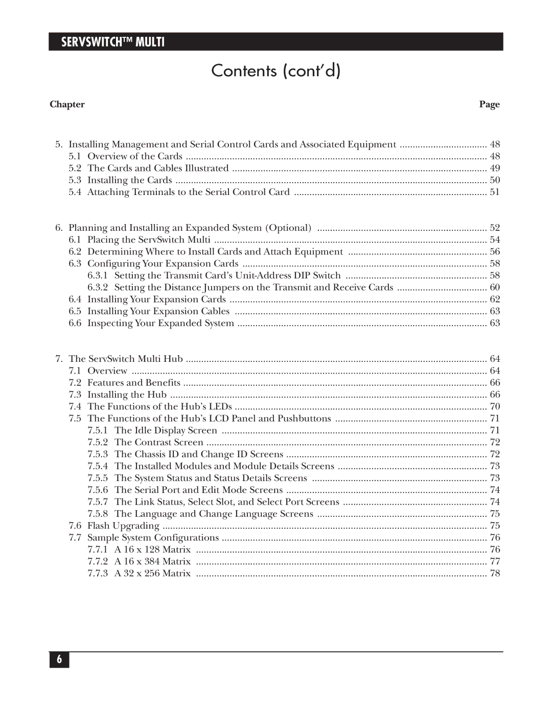
5. | Installing Management and Serial Control Cards and Associated Equipment | .................................. 48 | |
| 5.1 | Overview of the Cards | 48 |
| 5.2 | The Cards and Cables Illustrated | 49 |
| 5.3 | Installing the Cards | 50 |
| 5.4 | Attaching Terminals to the Serial Control Card | 51 |
6. | Planning and Installing an Expanded System (Optional) | 52 | |
| 6.1 | Placing the ServSwitch Multi | 54 |
| 6.2 | Determining Where to Install Cards and Attach Equipment | 56 |
| 6.3 | Configuring Your Expansion Cards | 58 |
|
| 6.3.1 Setting the Transmit Card’s | 58 |
|
| 6.3.2 Setting the Distance Jumpers on the Transmit and Receive Cards | 60 |
| 6.4 | Installing Your Expansion Cards | 62 |
| 6.5 | Installing Your Expansion Cables | 63 |
| 6.6 | Inspecting Your Expanded System | 63 |
7. | The ServSwitch Multi Hub | 64 | |
| 7.1 | Overview | 64 |
| 7.2 | Features and Benefits | 66 |
| 7.3 | Installing the Hub | 66 |
| 7.4 | The Functions of the Hub’s LEDs | 70 |
| 7.5 | The Functions of the Hub’s LCD Panel and Pushbuttons | 71 |
|
| 7.5.1 The Idle Display Screen | 71 |
|
| 7.5.2 The Contrast Screen | 72 |
|
| 7.5.3 The Chassis ID and Change ID Screens | 72 |
|
| 7.5.4 The Installed Modules and Module Details Screens | 73 |
|
| 7.5.5 The System Status and Status Details Screens | 73 |
|
| 7.5.6 The Serial Port and Edit Mode Screens | 74 |
|
| 7.5.7 The Link Status, Select Slot, and Select Port Screens | 74 |
|
| 7.5.8 The Language and Change Language Screens | 75 |
| 7.6 | Flash Upgrading | 75 |
| 7.7 | Sample System Configurations | 76 |
|
| 7.7.1 A 16 x 128 Matrix | 76 |
|
| 7.7.2 A 16 x 384 Matrix | 77 |
|
| 7.7.3 A 32 x 256 Matrix | 78 |
6
