CHAPTER 4: Installing CPU-Interface Cards, Server Cables, and Computers
4.4.2FOR APPLE MACINTOSH COMPATIBLE COMPUTERS
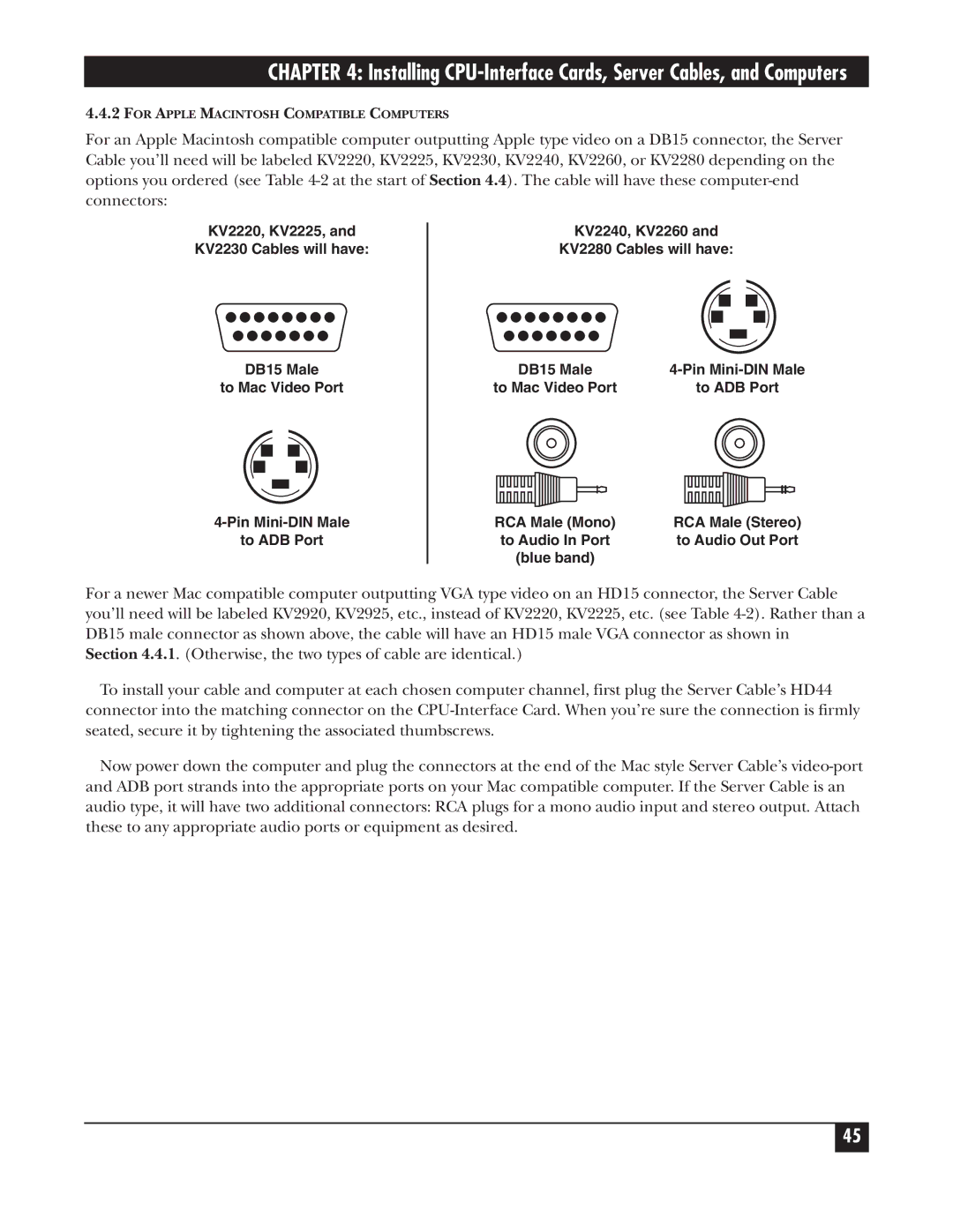
For an Apple Macintosh compatible computer outputting Apple type video on a DB15 connector, the Server Cable you’ll need will be labeled KV2220, KV2225, KV2230, KV2240, KV2260, or KV2280 depending on the options you ordered (see Table
KV2220, KV2225, and
KV2230 Cables will have:
KV2240, KV2260 and
KV2280 Cables will have:
DB15 Male
to Mac Video Port
DB15 Male | |
to Mac Video Port | to ADB Port |
to ADB Port
RCA Male (Mono) | RCA Male (Stereo) |
to Audio In Port | to Audio Out Port |
(blue band) |
|
For a newer Mac compatible computer outputting VGA type video on an HD15 connector, the Server Cable you’ll need will be labeled KV2920, KV2925, etc., instead of KV2220, KV2225, etc. (see Table
Section 4.4.1. (Otherwise, the two types of cable are identical.)
To install your cable and computer at each chosen computer channel, first plug the Server Cable’s HD44 connector into the matching connector on the
Now power down the computer and plug the connectors at the end of the Mac style Server Cable’s
45