Black Box KV162A manual Installing User-Interface Cards in a ServSwitch Multi, Servswitch Multi

Models: KV162A

1 159
Download 159 pages 52 Kb
Page 29
Image 29
3.2 Installing User-Interface Cards in a ServSwitch Multi

SERVSWITCH™ MULTI

3.2 Installing User-Interface Cards in a ServSwitch Multi

To install a Universal User-Interface Card (“UUIC” for short, our product code KV2500C) or User-Interface Card with On-Screen Display (“UICD” for short, our product code KV2550C-R2) in a ServSwitch Multi Base Unit, MX, EXP, or SB, take these steps:

1.Position the ServSwitch Multi so that its rear panel is facing you, as shown in Figure 3-3 on the next page. Choose an available slot. In most cases, any slot that is covered with a blank (connectorless) panel will be available. However, note that on the Base Unit and MX, the local-console module on the far left end of the Switch’s rear panel is covered by a blank panel but is not an available slot; no ServSwitch Multi Card of any type can be installed in that slot. Remember that the option slot (the slot just to the right of the local- console module, which has no corresponding front-panel LED or pushbutton) is an available slot and should preferably host a User-Interface Card, Expansion Card, etc., rather than a CPU-Interface Card.

2.Once you’ve chosen the slot, write down the letter of the corresponding channel in the “Channe Letterl” field of this Card’s record in a copy of the User-Interface Cards pages of the System-Configuration Chart (see Appendix A). At this time you should also write down what appears on the Card’s label (just to the right of the HD62 connector if you look at the connector from the rear) in the Chart’s “Card-Label Information” field, and (if the ServSwitch Multi unit is part of a cascaded system) you should write down the Switch’s address in the “Switch Address” field as well.

3.Remove the panel covering the available slot by unscrewing the two Phillips-head screws that hold it in place. (Save these screws; you’ll be replacing them momentarily.)

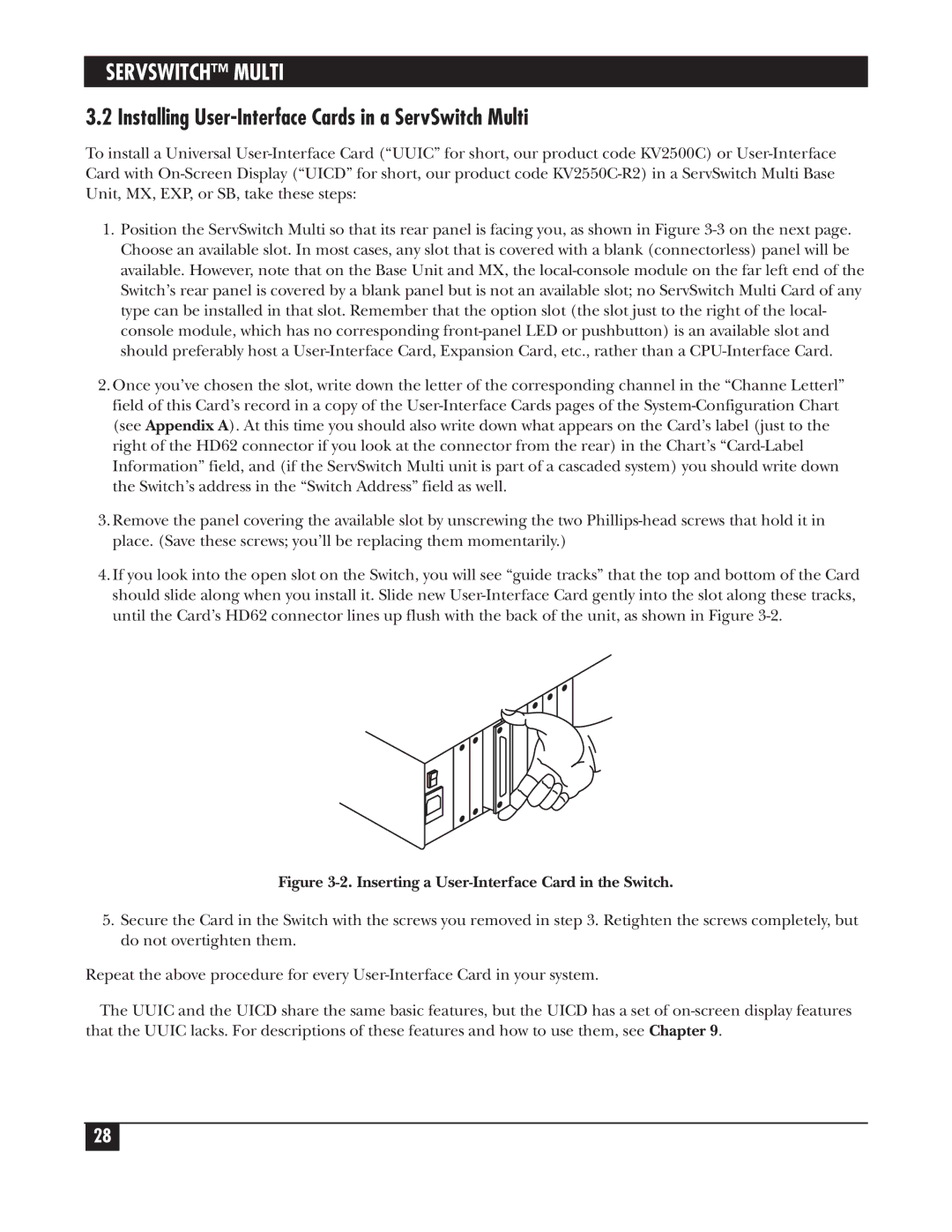
4.If you look into the open slot on the Switch, you will see “guide tracks” that the top and bottom of the Card should slide along when you install it. Slide new User-Interface Card gently into the slot along these tracks, until the Card’s HD62 connector lines up flush with the back of the unit, as shown in Figure 3-2.

Figure 3-2. Inserting a User-Interface Card in the Switch.

5.Secure the Card in the Switch with the screws you removed in step 3. Retighten the screws completely, but do not overtighten them.

Repeat the above procedure for every User-Interface Card in your system.

The UUIC and the UICD share the same basic features, but the UICD has a set of on-screen display features that the UUIC lacks. For descriptions of these features and how to use them, see Chapter 9.

28

Page 29
Image 29
Black Box KV162A manual Installing User-Interface Cards in a ServSwitch Multi, Servswitch Multi