CHAPTER 7: The ServSwitch Multi Hub
NOTE
If it will be easier for you to configure your Modules while you’re looking at cables you’ve already installed, feel free to attach your expansion cables to any given Module (refer to step 6) before you do steps 3 through 5.
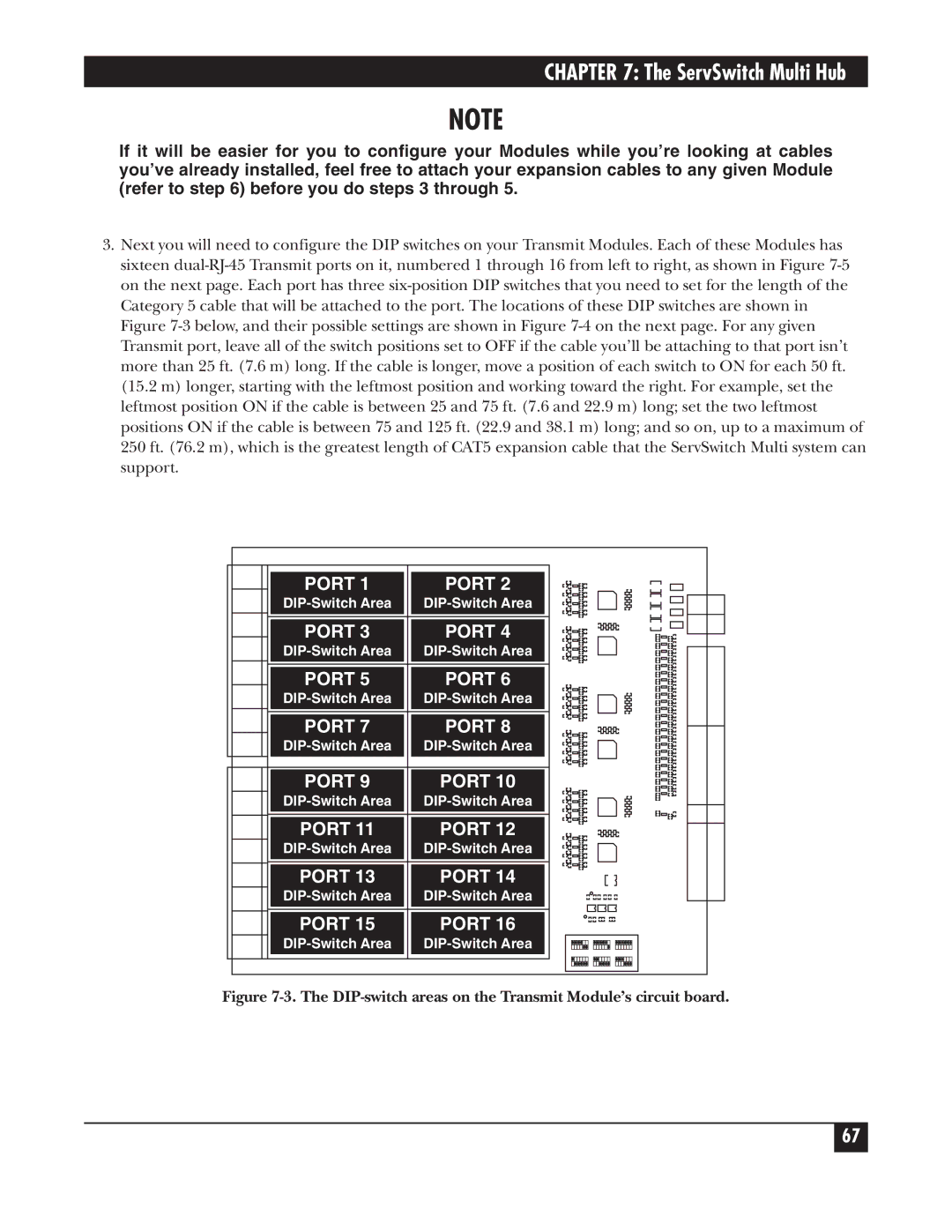
3.Next you will need to configure the DIP switches on your Transmit Modules. Each of these Modules has sixteen dual-RJ-45 Transmit ports on it, numbered 1 through 16 from left to right, as shown in Figure 7-5 on the next page. Each port has three six-position DIP switches that you need to set for the length of the Category 5 cable that will be attached to the port. The locations of these DIP switches are shown in Figure 7-3 below, and their possible settings are shown in Figure 7-4 on the next page. For any given Transmit port, leave all of the switch positions set to OFF if the cable you’ll be attaching to that port isn’t more than 25 ft. (7.6 m) long. If the cable is longer, move a position of each switch to ON for each 50 ft. (15.2 m) longer, starting with the leftmost position and working toward the right. For example, set the leftmost position ON if the cable is between 25 and 75 ft. (7.6 and 22.9 m) long; set the two leftmost positions ON if the cable is between 75 and 125 ft. (22.9 and 38.1 m) long; and so on, up to a maximum of 250 ft. (76.2 m), which is the greatest length of CAT5 expansion cable that the ServSwitch Multi system can support.
PORT 1 | PORT 2 |
DIP-Switch Area | DIP-Switch Area |
PORT 3 | PORT 4 |
DIP-Switch Area | DIP-Switch Area |
PORT 5 | PORT 6 |
DIP-Switch Area | DIP-Switch Area |
PORT 7 | PORT 8 |
DIP-Switch Area | DIP-Switch Area |
PORT 9 | PORT 10 |
DIP-Switch Area | DIP-Switch Area |
PORT 11 | PORT 12 |
DIP-Switch Area | DIP-Switch Area |
PORT 13 | PORT 14 |
DIP-Switch Area | DIP-Switch Area |
PORT 15 | PORT 16 |
DIP-Switch Area | DIP-Switch Area |
Figure 7-3. The DIP-switch areas on the Transmit Module’s circuit board.