Black Box KV162A manual Servswitch Multi, 5. Inserting a CPU-Interface Card in the Switch

Models: KV162A

1 159
Download 159 pages 52 Kb
Page 43
Image 43
Figure 4-5. Inserting a CPU-Interface Card in the Switch.

SERVSWITCH™ MULTI

2.Once you’ve chosen the slot, write down the letter of the corresponding channel in the “Channel Letter” field of this Card’s record in a copy of the CPU-Interface Card pages of the System-Configuration Chart (see Appendix A). At this time you should also write down what appears on the Card’s label (just to the right of the HD44 connector if you look at the connector from the rear) in the Chart’s “Card-Label Information” field, and (if the ServSwitch Multi unit is part of a cascaded system) you should write down the Switch’s address in the “Switch Address” field as well.

3.Remove the panel covering the available slot by unscrewing the two Phillips-head screws that hold it in place. (Save these screws; you’ll be replacing them momentarily.)

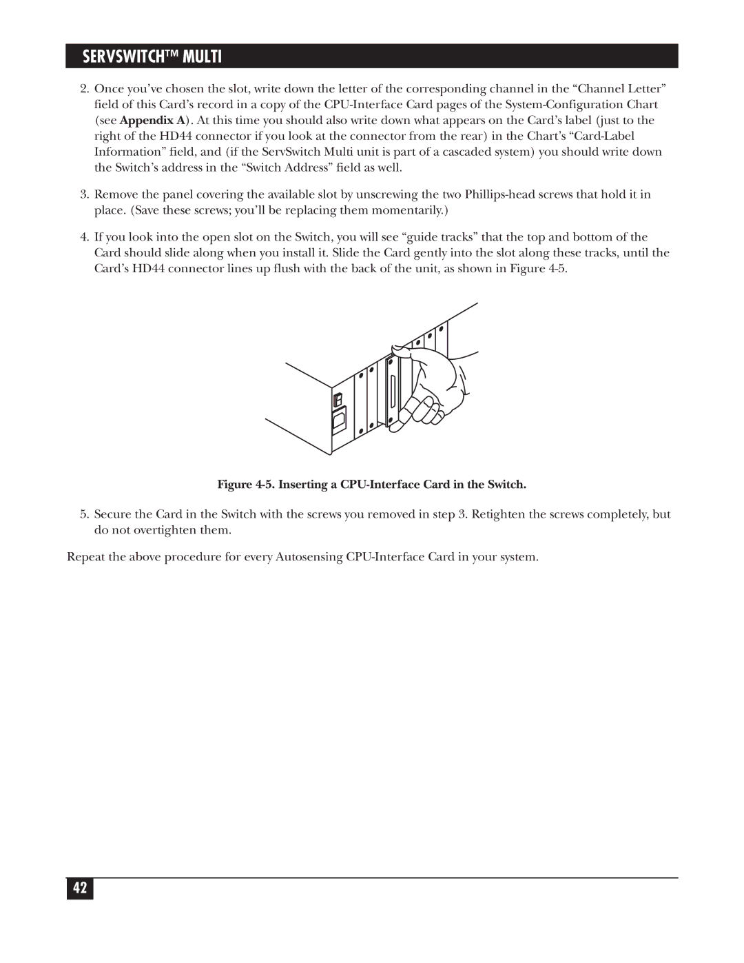
4.If you look into the open slot on the Switch, you will see “guide tracks” that the top and bottom of the Card should slide along when you install it. Slide the Card gently into the slot along these tracks, until the Card’s HD44 connector lines up flush with the back of the unit, as shown in Figure 4-5.

Figure 4-5. Inserting a CPU-Interface Card in the Switch.

5.Secure the Card in the Switch with the screws you removed in step 3. Retighten the screws completely, but do not overtighten them.

Repeat the above procedure for every Autosensing CPU-Interface Card in your system.

42

Page 43
Image 43
Black Box KV162A manual Servswitch Multi, 5. Inserting a CPU-Interface Card in the Switch